|
|
|
Who's Online
There currently are 6043 guests online. |
|
Categories
|
|
Information
|
|
Featured Product
|
|
|
 |
|
|
There are currently no product reviews.
 ;
This manual was the factory original. Excellent value and contained all the details I needed. Easy dowwnload provided the information when I needed it.
 ;
Impeccable, document très complet. Perfect, i get all i need. All schematic are correct. Thanks
;
The manual is of better quality compared to other. I found it less expensive and therefore it it is the best buy cost vs quality.
;
I bought the service-manual of the sony ICB-1020(an old transmitter-receiver) at "www.Owners-Manual.com", I found the service-manual for a fairly cheap price(in comparison with other sellers). I filled in some questions, payed the order with Ideal, and within 24 hours I had my service manual. I was very happy:In no time I had my service-manual and everything, but literally everything was noted down in the manual; the electronic scheme, the parts list, etcetera.
A very practical, reference-document.
;
This comprehesive service maual was greatly appreciated, as was the digital download.
5
6
7
8
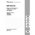
6.5 MECHANISM ADJUSTMENT
A
1 Tangential and Radial Height Coarse Adjustment START
� Remove the 06SD Pickup Assy from the Traverse Mechanism Assy-S. � Remove the joint and the joint spring of the 06SD Pickup Assy.
06SD Pickup Assy
Joint VK1B
Note: Before removing the flexible cable for the pickup, soldering of the pickup circuit is necessary. For details, see "7.1.14 DISASSEMBLY".
Joint spring VK1 Hold spring
B
� Pass through the guide shaft to a new 06SD Pickup Assy. � Attach it to the Traverse Mechanism Assy-S.
06SD Pickup Assy
C
Guide Shaft
D
� Put the joint between the Tangential (or Radial) adjustment screw and the mechanism base and turn each screw to adjust the height. (Refer to "6.1 ADJUSTMENT ITEMS AND LOCATION".)
Joint
7.5mm Mechanism base
E
� Attach the Traverse Mechanism Assy-S to the 06 LOADER Assy. � Turn it over and attach the joint and the joint spring. � Arrange the flexible cables. (Refer to "7.1.14 DISASSEMBLY".)
F
XV-MF5
5 6 7 8
71
|
|
|
> |
|