|
|
|
Who's Online
There currently are 6013 guests online. |
|
Categories
|
|
Information
|
|
Featured Product
|
|
|
 |
|
|
There are currently no product reviews.
 ;
Exactly as described, a Service Manual complete with the schematics and PCB layout delivered in a timely manner. Many thanks for the great service.
 ;
some of the writing is a bit blur but the part in the schmatic was great and i have fixed the machine thanks
;
Well.. I'd searched for this manual and although I found many copies online I was pleased to find your website with a well balanced pricing system and easy to search and follow links. That together with the very quick response time was just what I was looking for.. being a very impatient tech.. ;-) I had the service manual in front of me within a short time.
Bookmarked.. and you can bet I will always come here first for my service & user manuals..
best regards
Ed(Tony) Foley
G7WHK
;
I will definitely be back for more information when I need it.
;
The service manual when downloaded and printed out was clear and easy to read. I would have liked to have been able to enlarge some details, but this was not possible as the file permissions did not allow this. The service was very good. The time taken from placing my order to downloading the document was only a few minutes.
5
6
7
8
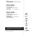
7. DISASSEMBLY
Note 1: Do NOT look directly into the pickup lens. The laser beam may cause eye injury. Note 2: Even if the unit shown in the photos and illustrations in this manual may differ from your product, the procedures described here are common.
A
Diagnosis of PCB's
1 Bonnet, Tray Panel
1 2 3 4 5 6 7 8
Remove the bonnet by removing the nine screws. Press the � STANDBY/ON button to turn on the power. Press the � OPEN/CLOSE button to open the tray. Remove the tray panel. Set the test disc. Press the � OPEN/CLOSE button to close the tray. (Test disc is clamped.) Press the � STANDBY/ON button to turn off the power. Pull out the Power cord. Test disc
27
B
5 4
3
6
Tray panel
Tray
36
C
D
How to open the tray when the power cannot be on
Insert a screwdriver (small) into the slit located at the bottom of the unit, and slide the projection of the drive cam in the 06 LOADER Assy in the direction of the arrow, as indicated in the photo. If the tray pops out a little, fully pull it out by hand.
Projection
Screwdriver (small)
E
Slit Tray open
Drive cam 06 LOADER Assy Bottom view Screwdriver (small)
F
XV-DV363
5 6 7 8
33
|
|
|
> |
|