|
|
|
Who's Online
There currently are 6041 guests and
2 members online. |
|
Categories
|
|
Information
|
|
Featured Product
|
|
|
 |
|
|
There are currently no product reviews.
 ;
This is the original manufacturers service manual, with detailed info on the circit boards, explosion drawings of all parts in assembly order, and tuning instructions. The only thing missing is the information on the dimensions of the various drive belts. mail me if you need them. gcrossman_at_aol.com
;
Ordered service manuel for a hard to find plasma tv - your company made it easy to find and purchase - I will use you again
Thanks for your help
 ;
This is a high quality manual with clear schematic and components layout diagrams ; with service procedure included.
;
This service manual for the Kenwood KT-990D was reproduced really well ,is very legible and manual is complete.Combined with the low price paid,in the future,I will be checking Owner-Manuals.com any time I need a manual.
;
When I purchased this manual I had my doubts regarding the quality as the price was so reasonable as compared to other outlets.
The manual itself is of high standard the print is very clear as are the diagrams. Obviously with the diagrams one has to zoom in otherwise it is to small to be able to read.
Overall I am very pleased with the company who delivered as they said and with the manual they supplied.
I occasionally require a manual and now having registered with this company I shall order from them in the future.
1
2
3
4
A
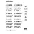
Removing the Traverse Mechanism Assy-S and 06SD Pickup Assy-S
1 06 LOADER Assy
1
Short-circuit point by soldering.
Note: After replacement, connect the flexible cable, then remove the soldered joint (open).
3
4
3
B
2 3 4
Disconnect the four connectors. Remove the two screws. Remove the 06 LOADER Assy.
06 LOADER Assy Rear view 06SD Pickup Assy-S
C
2 2
22
Note: Do not touch the bottom side of the 06SD Pickup Assy-S. If touched, the optical axis may be shifted.
1
DVD MAIN Assy
2 Bridge 04, Tray
D
1 2 3
Remove the one screw. Remove the bridge 04. Pull out the tray, then remove it by pressing the hook.
1 3
-2
2
Hook
E
Tray Bridge 04
3
Note when reinserting the tray
When reinserting the tray, first align the triangle printed on the loading base and the pin of the drive cam, then insert the tray.
-1
Drive cam
Pin
F
Front side Loading base Triangle
4
38
1 2
XV-CX505
3
|
|
|
> |
|