|
|
|
Who's Online
There currently are 5880 guests and
4 members online. |
|
Categories
|
|
Information
|
|
Featured Product
|
|
|
 |
|
|
There are currently no product reviews.
 ;
Very good documentation for the Grundig 2077 model (as well as similar 800/900/1000 series radios). The first two pages are a summary of reception specifications and output capability. The third page is the tuner dial indicator and dial cord routing diagram. the final ~5 pages are the schematics for the various models (including 2077). The scan quality of the schematics are good, adn can be easily read if zoomed in. The documents are in German, not English as stated. It would have been nice to have the tuning sequence and settings, and some trouble shooting materials... or component and wiring map.
 ;
Perfect like it was descriped, Perfect like it was descriped
;
Very good detail, all pages clear, exactly what I needed
;
Excellent service, and just what I needed to service my TU-7700. All pages of the manual are clear and easily readable.
;
Excellent printing quality.
A complete and very usefull service manual with all details.
GREAT SERVICE AT VERY LOW PRICE!
A+++++++++++++++++++++++++
XR-VS99
6. ADJUSTMENT
6.1 TUNER SECTION
FM Tuner Section
� Set the mode selector to FM BAND. � Connect the wiring as shown in Fig. 1.
Step No. 1 2 Adjustment Title Front End Sensitivity TUNED IND. Lighting Level FM SG (1kHz, ± 75kHz dev.) Frequency (MHz) 98 98 Level (dBµV) 0-30 18 ± 2 Reception Frequency Display 98MHz 98MHz Adjustment Location L6402 T6401 VR6201 Specifications Adjust so that the DC voltage between the IC6201pin 20 and GND becomes at maximum level. Adjust so that the indicator of TUNED IND. starts to light up.
Note: Before adjusting, make sure there is no gap between L6401 and L6402. If there is a gap between them, bring them into contact with each other first, and then make adjustments.
� Set the mode selector to AM BAND. � Connect the wiring as shown in Fig. 1.
Step No. 1 Adjustment Title Front End Sensitivity AM SG (400Hz, 30% Mod.) Frequency (kHz) 999 (*1) Level (dBµV/m) 35-45 Reception Frequency Display 999kHz (*1) Adjustment Location T6201 Specifications Adjust so that the DC voltage between the IC6201pin 20 and GND becomes at maximum level.
AM Tuner Section
Note (*1): For the area using 10kHz step, frequencies should be 1000kHz.
60cm Loop antenna
AM SG
Center
Center
AM antenna terminal
MPX SG
FM SG
PRODUCT
DC Voltmeter
FM75� antenna terminal
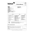
Fig. 1 AM and FM Adjustment Wiring Diagram
FM/AM TUNER MODULE
AM antenna terminal
SIDE A
T6201
YELLOW
BLACK AXX7041 IC6201 Pin 20 VR6201 T6401 L6401
FM antenna terminal
L6402
Fig. 2 Adjustment Point
55
|
|
|
> |
|