|
|
|
Who's Online
There currently are 5880 guests online. |
|
Categories
|
|
Information
|
|
Featured Product
|
|
|
 |
|
|
There are currently no product reviews.
 ;
Great manual, great price. Has a few of the basic operating instructions that most service manuals leave out. Complete instructions for disassembling board by board, safety precautions, schematics, complete parts list.
;
I am very pleased with the service manual for my RT-909. This was an easy purchase and great procuct, and much cheaper than other venues i had looked at. This web site is now listed in my favorites list. KEEP UP THE GOOD WORK. THANKS. J. BROWN
;
A very well written and easy to understand manual.
;
There was no problem at all.After paying i had to wait only a few hours,than i could
download the manual in best pdf-quality.
Thank You !
 ;
I found this service manual to be complete in every detail except for troubleshooting charts. It would be helpful if it had a set of troubleshooting charts; however it is a very good manual otherwise and for the price it is very well worth it.
XR-A880, XR-A770
6. ADJUSTMENT
6.1 TUNER SECTION
FM Tuner Section
� Set the mode selector to FM BAND. � Connect the wiring as shown in Fig. 1.
Step No. 1 2 Adjustment Title Front End Sensitivity TUNED IND. Lighting Level FM SG (1kHz, ± 75kHz dev.) Frequency (MHz) 98 98 Level (dBµV) 0-30 18 ± 2 Reception Frequency Display 98MHz 98MHz Adjustment Location L6402 T6401 VR6201 Specifications Adjust so that the DC voltage between the IC6201pin 20 and GND becomes at maximum level. Adjust so that the indicator of TUNED IND. starts to light up.
Note: Before adjusting, make sure there is no gap between L6401 and L6402. If there is a gap between them, bring them into contact with each other first, and then make adjustments.
� Set the mode selector to AM BAND. � Connect the wiring as shown in Fig. 1.
Step No. 1 Adjustment Title Front End Sensitivity AM SG (400Hz, 30% Mod.) Frequency (kHz) 999 (�1) Level (dBµV/m) 35-45 Reception Frequency Display 999kHz (�1) Adjustment Location T6201 Specifications Adjust so that the DC voltage between the IC6201pin 20 and GND becomes at maximum level.
AM Tuner Section
Note (�1): For the area using 10kHz step, frequencies should be 1000kHz.
60cm Loop antenna
AM SG
Center
Center
AM antenna terminal
MPX SG
FM SG
PRODUCT
DC Voltmeter
FM75� antenna terminal
Fig. 1 AM and FM Adjustment Wiring Diagram
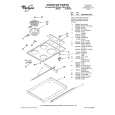
FM/AM TUNER MODULE
AM antenna terminal
SIDE A
T6201
YELLOW
BLACK AXX7041 IC6201 Pin 20 VR6201 T6401 L6401
FM antenna terminal
L6402
Fig. 2 Adjustment Point
55
|
|
|
> |
|