|
|
|
Who's Online
There currently are 6043 guests online. |
|
Categories
|
|
Information
|
|
Featured Product
|
|
|
 |
|
|
There are currently no product reviews.
 ;
Yes thank you i got the file i was after. There was a slight problem in my communication but it all worked out well.
A job well done.
 ;
Great manual...really saved me. The only problem is that I thought I would be able to download it directly when I paid for it but never received the download instructions until the next morning. The board trace pages were somewhat light also: really need to turn up the contrast on the printer before printing them. The schematic page was great; very clear! Well worth the money.
;
I've been in the electronic business for a long time. I used to buy Sam's Photofact for my needs which intailed having to go to the store and paying about $20 for a package of 3 different units so I was forced to buy more than I needed just to get one.
Owner manual is just at your keyboard and the information is almost instantansouly and the cost is very reasonable. Easy to print out if needed or simply read off of the screen. The larger the screen the better for obvious reasons.
;
Very good manual, at a very good price. Received in a timely manner
;
Only thу cover has poor quality, internal material has excellent quality - exactly what I needed
Thanks!
XR-A6800, XR-A4800
6. ADJUSTMENT
6.1 TUNER SECTION
FM Tuner Section
� Set the mode selector to FM BAND. � Connect the wiring as shown in Fig. 1. Step No. Adjustment Title FM SG (1kHz, ± 75kHz dev.) Frequency Level (MHz) (dBµV)
106 98 (ON STEREO) 98 0 to 30
Reception Frequency Display
106MHz
Adjustment Location
L6104 L6105 L6102 T6101 T6101 VR6201
Specifications
1
Front End Sensitivity Stereo Distortion TUNED IND. Lighting Level
Adjust so that the DC voltage between the IC6201 - pin 20 and GND becomes at maximum level. Minimize the distortion with 1/8 rotation of the core. Adjust so that the indicator of TUNED IND. starts to light up.
2 3
80 18 ± 2
98MHz 98MHz
Note: Before adjusting, make sure there is no gap between L6101 and L6102 as well as between L6103 and L6104. If there is a gap between them, bring them into contact with each other first, and then make adjustments.
AM Tuner Section
� Set the mode selector to AM BAND. � Connect the wiring as shown in Fig. 1. Step No. Adjustment Title
Front End Sensitivity
AM SG (400Hz, 30% Mod.) Frequency Level (kHz) (dBµV/m)
999 (�1) 35 to 45
Reception Frequency Display
999kHz (�1)
Adjustment Location
Specifications
Adjust so that the DC voltage between the IC6201 - pin 20 and GND becomes at maximum level.
1
T6201
Note (�1) : For the area using 10kHz step, frequency should be 1000kHz. 60cm Loop antenna
AM SG
Center
Center
AM antenna terminal DC Voltmeter
MPX SG
FM SG FM75� antenna terminal
PRODUCT
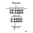
Fig.1 AM and FM Adjustment Wiring Diagram
FM/AM TUNER MODULE
AM antenna terminal T6201 AXX7042 YELLOW FM antenna terminal BLACK L6105 T6101 L6102 L6103 L6104
IC6201 Pin 20
VR6201
L6101
Fig.2 Adjustment Point
53
|
|
|
> |
|