|
|
|
Who's Online
There currently are 5795 guests online. |
|
Categories
|
|
Information
|
|
Featured Product
|
|
|
 |
|
|
There are currently no product reviews.
 ;
Dear Sirs,
Thank you for the fast support, the manual does provide all necessary information to repair the radio. All schematics are in a good quality for reading.
The manual fits 100% to my requirements as a technican.
Kind regards Thomas
;
the big video recorder format s-vhs many features delicate in loading system of the cassette. Such machines are no longer manufactured, it would be too expensive.
 ;
THIS MANUAL IS VERY GOOD AND VERY CLEAR
PLEASE NOTE IT DOES NOT CONTAIN THE SETUP INFORMATION TO ALIGHN THE GEARS IN THE CD MECH IT DOES SHOW ALL THE PARTS AND THEIR LOCATIONS .
;
Complete service and operation manual. All schematics are there, all circuit boards AND add-on boards. Including exploded views ,component names and specifications. Also electrical and mechanical adjustment procedures are in this manual. This manual also covers the more advanced BR-S811E unit. Scan quality is fair and usable.
;
High quality scan of original Service Manual. Everything´s fine!
XR-A6800, XR-A4800
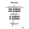
6. ADJUSTMENT
6.1 TUNER SECTION
FM Tuner Section
� Set the mode selector to FM BAND. � Connect the wiring as shown in Fig. 1. Step No. Adjustment Title FM SG (1kHz, ± 75kHz dev.) Frequency Level (MHz) (dBµV)
106 98 (ON STEREO) 98 0 to 30
Reception Frequency Display
106MHz
Adjustment Location
L6104 L6105 L6102 T6101 T6101 VR6201
Specifications
1
Front End Sensitivity Stereo Distortion TUNED IND. Lighting Level
Adjust so that the DC voltage between the IC6201 - pin 20 and GND becomes at maximum level. Minimize the distortion with 1/8 rotation of the core. Adjust so that the indicator of TUNED IND. starts to light up.
2 3
80 18 ± 2
98MHz 98MHz
Note: Before adjusting, make sure there is no gap between L6101 and L6102 as well as between L6103 and L6104. If there is a gap between them, bring them into contact with each other first, and then make adjustments.
AM Tuner Section
� Set the mode selector to AM BAND. � Connect the wiring as shown in Fig. 1. Step No. Adjustment Title
Front End Sensitivity
AM SG (400Hz, 30% Mod.) Frequency Level (kHz) (dBµV/m)
999 (�1) 35 to 45
Reception Frequency Display
999kHz (�1)
Adjustment Location
Specifications
Adjust so that the DC voltage between the IC6201 - pin 20 and GND becomes at maximum level.
1
T6201
Note (�1) : For the area using 10kHz step, frequency should be 1000kHz. 60cm Loop antenna
AM SG
Center
Center
AM antenna terminal DC Voltmeter
MPX SG
FM SG FM75� antenna terminal
PRODUCT
Fig.1 AM and FM Adjustment Wiring Diagram
FM/AM TUNER MODULE
AM antenna terminal T6201 AXX7042 YELLOW FM antenna terminal BLACK L6105 T6101 L6102 L6103 L6104
IC6201 Pin 20
VR6201
L6101
Fig.2 Adjustment Point
53
|
|
|
> |
|