|
|
|
Who's Online
There currently are 5705 guests online. |
|
Categories
|
|
Information
|
|
Featured Product
|
|
|
 |
|
|
There are currently no product reviews.
 ;
Thanks God for the internet and thanks for the service like this - proffessional solution on time.
;
About the service it's very fast and reliable. About the manual the quality is high enough to read even the tiniest details on the wiring diagrams so you can't ask much more than that, let it alone for a manual of a product from 20 years ago. Thank you, very satisfied.
;
The downloaded quality was as good as the orignial
 ;
This is a great and complete Service Manual for the Sharp GF8585HB. Giving full and detailed technical insight. Good to find these manuals online.
;
Everything was ok with the manual. If I have a small complaint, is that I ordered it during the weekend and I think you guys were closed. But I did receive it late Sunday. I will surely order from you again
XR-A670, XR-A370
6.2.2 For XR-A370
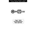
� Adjustment points and test points are shown in Fig.10, Fig.12 and Fig.13.
Mechanical Adjustment
� Test tape : NCT-111 (3kHz, 30min).
1. Tape Speed Adjustment
No. Mode Test Tape Adjusting Points Measurement Points
TAPE TEST POINT (Rch) (AF Assy)
Adjustment Procedure
Press the PLAY SW and adjust so that the reading becomes 3000Hz ± 20Hz. Confirm that wow & flutter level is below 0.3% (in the reverse direction, confirm that the reading is within 3000Hz ± 60Hz).
Remarks
1
Deck � PLAY
ADJ. VR on NCT-111 CASSETTE (Playback : 3kHz) MECHA (Fig. 10)
Tape Speed ADJ. VR AF Assy Front Side Cassette Mechanism Section (Side View)
Fig.10 Tape Speed ADJ. Point
Electrical Adjustment
Check the following before starting.
(1) Confirm that the tape speed adjustment has been completed. (2) Clean the heads and demagnetize them using a head eraser. (3) Set the measurement level to 0 dBV = 1 Vrms. (4) Use the specified tape for adjustment. Use the labeled (A) side of the test tape. STD-331E : For playback check STD-632 : Normal blank tape (5) Provide yourself with the following measuring devides: � AC voltmeter (Noisemeter : filter off) � AC millivoltmeter � Low-frequency oscillator � Attenuator � Oscilloscope (6) Adjust both right and left channels unless otherwise specified. (7) Warm up the unit for several minutes before adjustment. In particular, be sure to warm up the unit in the REC/PLAY mode for 3 to 5 minutes before starting recording/playback frequency characteristics adjustment. (8) Always follow the indicated adjustment order. Otherwise, a complete adjustment may not be achieved.
Playback Adjustment (Decks � and ��)
(1) Head Azimuth Adjustment
Recording Adjustment (Deck �)
(1) Bias Oscillation Frequency Adjustment (2) Recording Bias Adjustment � As the reference recording level is 250nwb/m for STD-331E, the recording level will be higher by 4 dB for STD-331B (160nwb/m). When adjusting, pay carefull attention to the type of tape used.
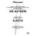
0 dB 30s 315Hz
0 dB: 315 Hz, 250 nwb/m 30s 6.3kHz 30s 10kHz 30s 315Hz 10s ......................................................................................................... 10s �20 dB 12.5 6.3 500 250 125 14kHz kHz 10kHz 8kHz kHz 4kHz 2kHz 1kHz Hz Hz Hz 63Hz 40Hz 10s
Fig.11 STD-331E Test Tape 63
|
|
|
> |
|