|
|
|
Who's Online
There currently are 6042 guests and
1 member online. |
|
Categories
|
|
Information
|
|
Featured Product
|
|
|
 |
|
|
There are currently no product reviews.
 ;
Top quality manual. Covers all aspects you'd expect in a top quality service manual for this Panasonic VHS VCR. The manual resolution is high. Another top quality manual from the only site worth downloading manuals from! If you're looking for a manual for the PV-9662 VHS VCR, this is the one you'll want to get!
;
complete part-lists and pcb layout, schematic diagram is good enlargable,
;
Excellent, fast delivery, excellent product. Good luck!
;
This manual is for the usa model only. But it is clear
, accurate and comprehensive, including board layouts and schematics.
I found it extremely useful for my mitsubishi dp-86da, but the same diagram would also work for the realistic lab5000 and hi fi 80. Thanks.
;
Great to have extra resources for Service Manuals, Now days you can really not trouble shoot efficiently without one , Wayne at IRIONS TV & ELECTRONICS REPAIR Clearwater , Fl. 33755 727-446-7955
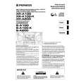
XR-A100, XR-A100-K
5. ADJUSTMENT
Note: Adjustment of MYXK, NVXK and YPWXJ types are the same as those of base model except for the following.
5.1 FM/AM TUNER MODULE (AXQ7077: MYXK and NVXK types only)
7 FM Tuner Section
÷ Set the mode selector to FM BAND. ÷ Connect the wiring as shown in Fig. 1. FM SG (1kHz, ±75kHz dev.) Reception Step No. Adjustment Title Frequency (MHz)
1 Front End Sensitivity Stereo Distortion TUNED IND. Lighting Level
Level (dBµV) 0 to 30
Frequency Display 106 MHz
Adjustment Location
L6104 L6105 L6102 T6101 T6101
Specifications
106
Adjust so that the DC voltage between the IC6201Pin 20 and GND becomes at maximum level. Minimize the distortion with 1/8 rotation of the core. Adjust so that the indicator of TUNED IND. starts to light up.
2
98
(ON STEREO)
80 18 ± 2
98 MHz 98 MHz
3
98
VR6201
Note: Before adjusting, make sure there is no gap between L6101 and L6102 as well as between L6103 and L6104. If there is a gap between them, bring them into contact with each other first, and then make adjustments.
7 AM Tuner Section
÷ Set the mode selector to AM BAND. ÷ Connect the wiring as shown in Fig. 1. Step No. Adjustment Title AM SG (400Hz, 30% Mod.) Reception Frequency Adjustment Level Frequency Location Display (kHz) (dBµV/m) 999*1 35 to 45 999kHz*1 T6201 Specifications
1
Front End Sensitivity
Adjust so that the DC voltage between the IC6201Pin 20 and GND becomes at maximum level.
*1: For the area using 10kHz step, frequencies should be 1000 kHz.
60cm Loop antenna
AM SG
Center
Center
AM antenna terminal DC Voltmeter
MPX SG
FM SG FM75� antenna terminal
PRODUCT
Fig. 1
AM and FM Adjustment Wiring Diagram
27
|
|
|
> |
|