|
|
|
Who's Online
There currently are 5668 guests online. |
|
Categories
|
|
Information
|
|
Featured Product
|
|
|
 |
|
|
There are currently no product reviews.
 ;
Very good manual. Plenty of service information including alignment instructions. Clear circuit diagram. Excellent, thank you.
 ;
Good morning, the service manual you sent me was perfect.
Your service and answering are excellent.
I recomend this service.
Best regards.
;
I had been looking everywhere for a proper service manual for this VCR. Everywhere else that has this available for download has a very light version. This is the full service manual with all aspects that would interest anyone looking for the service manual for the AIWA HV-MX100 Worldwide VHS VCR. Great quality (as always). A winner hands down. Best Quality.
;
Top quality manual. Covers all aspects you'd expect in a top quality service manual for this Panasonic VHS VCR. The manual resolution is high. Another top quality manual from the only site worth downloading manuals from! If you're looking for a manual for the PV-9662 VHS VCR, this is the one you'll want to get!
;
complete part-lists and pcb layout, schematic diagram is good enlargable,
5
6
7
8
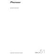
2. Diagnosis
1 POWER AMP Assy
A
1 2 3 4 5
Remove the Rear Panel. Remove the MAIN Assy (equipped with HDMI&DVC Assy and DSP&USB Assy) and the AUDIO IN Assy from the INTERFACE Assy. Discharge C5721 and C5722. (See the "discharge procedures.") Remove the two screws that fix the Regulators attached to the Chassis. Remove the two Push Rivets and the two screws that fix the POWER AMP Assy. Regulator
9
Remove the Locking Card Spacer from the Chassis using Cutting Pliers.
B
Locking Card Spacer (for fixing the Assy)
9 10 11 12 4 13
Cutting Pliers
Remove the four screws that fix the Heat Sink V5S. Cut the Binder. Remove the four screws that fix the Power Transformer. Place a high insulating material under the Power Transformer to raise it. Raise the block and diagnose the POWER AMP Assy B side.
C
Push Rivet
POWER AMP Assy
DIODE Assy
6
D
POWER AMP Assy
5
Caution: Fix the DIODE Assy to the Rear Panel with Tape so that it will not come closer to other Assy.
Tape DIODE Assy
E
6 7 8
Remove the two screws that fix the diode of the DIODE Assy. Reassembling the MAIN Assy (equipped with HDMI&DVC Assy and DSP&USB Assy) and the AUDIO IN Assy to the INTERFACE Assy. Reassembling the Rear Panel. (Keep a space for earth and about six to seven screws fixing places. Do not attach screws with the Chassis.)
Diagnosis
F
VSX-LX51
5 6 7 8
69
|
|
|
> |
|