|
|
|
Who's Online
There currently are 5935 guests online. |
|
Categories
|
|
Information
|
|
Featured Product
|
|
|
 |
|
|
There are currently no product reviews.
 ;
got exactly what i ordered in a very timely manner. will use again for other manuals
 ;
I'm happy. Good quality. Very helped me with my work..............................
;
This is the second Manual I have ordered from owner-manuals, I give it five stars because it is exactly what I expected given the age of the equipment. So the contents look a bit aged and the pictures a bit grainy, it fulfills my needs and I am glad I can still get hold of them.
;
thank u so much for this manual that was so cheap that i thought it was a scam but i gambled anyway because it was too good of a deal to pass up and behold,the manual has everything and details of everything even the screws and im still amazed and very happy with my manual .so take my word and jump on it before they realize how cheap they selling thier manuals..thank you so much for taking time to read my thoughts
;
I do not have very much to say.
The price is quite covenient, delivery was better as promised (about 12 ours, against the specified 24 hours if I remember well), and the quality of the PDF is more than acceptable.
The Service Manual of Sansui R30 itself is also satisfactory: good graphic for schematics and layouts, simple and well structured.
Giovanni Bianchi
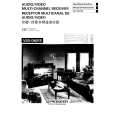
VSX-D607S
6. ADJUSTMENT
6.1 TUNER ADJUSTMENT
� Set the FM/AM selector to FM BAND. � Connect the wiring as shown in Fig. 6�1.
Step No. Adjustment Title Frequency (MHz) 98 Non modulation 98 98 98
ADJUSTMENT OF FM TUNER SECTION
FM SG (1kHz, ± 75kHz dev.) Level (dBµV) 80 or more Low input (0 to 30) 80 15 (± 2dB)
Reception Frequency Display �
Adjustment Location
Specifications Adjust so that the DC voltage between IC6201-pin 4 and pin 28 (or leads of C6224 and C6261) becomes 0V ± 50mV. Adjust so that the DC voltage between IC6201-pin 12 and GND (or leads of C6238 and GND) becomes at maximum level. Minimize the distortion with 1/8 rotation of the core. Adjust so that the indicator of TUNED IND. starts to light up.
1
Center Adjustment Front End Sensitivity Adjustment Stereo Distortion TUNED IND. Lighting Level
L6207 L6102 T6101 T6101 VR6201
2 3 4
98MHz 98MHz 98MHz
Notes: � Before adjusting, make sure there is no gap between L6101 and L6102 . If there is a gap between them, bring them into contact with each other first, and then make adjustments. � Make indicator adjustments in order of AM�FM.
� Set the FM/AM selector to AM BAND. � Connect the wiring as shown in Fig. 6�1.
Step No. 1 Adjustment Title TUNED IND. Lighting Level Frequency (kHz) 999 �1
ADJUSTMENT OF AM TUNER SECTION
AM SG (400Hz, ± 30% Mod.) Level (dBµV/m) 47 (± 2dB)
Reception Frequency Display 999kHz �1
Adjustment Location VR6202
Specifications Adjust so that the indicator of TUNED IND. starts to light up.
�1 : For the area using 10kHz step, frequencies should be 1000kHz.
51
|
|
|
> |
|