|
|
|
Who's Online
There currently are 5973 guests online. |
|
Categories
|
|
Information
|
|
Featured Product
|
|
|
 |
|
|
There are currently no product reviews.
 ;
Exactly what was needed to assess the product - excellent value and great service
 ;
Nice to have the service manual for the Sony DCR-TRV345E now. The document is of excellent quality.
;
MACKIE HR824 26 pages English-only Service Manual contains:
1) HR824 technical overview with the description of front and rear panel switches.
2) HR824 specs
3) Block Diagram
4) Wiring Diagram
5) Packaging management
6) Spare part & final assembly list (for PCB rev A and B) + exploded view
7) Test Procedures (where, how to measure voltage...) including Test Point diagram on the PCB.
8) IC and Transistor charts.
Excellent guide: very clear, good scan quality enabling us to print readable diagram :-)
Note:
Mackie HR824 make extensive use of surface mount devices (SMD). Service on the HR824 must
only be undertaken by experienced service technicians with the right tools, experience and patience to perform surface mount rework when needed.
;
This Service manual is very well scanned and its clean to read, no any anti-theft words that un-english could understand. I got my CCD600 working with this manual and it´s clear shematics :)
;
I was very pleased with the service provided and was surprised at how good the quality was of the manual. I thought it may be a third generation copy or so, but it is as good as the websites that charge 3 times this much. I repair some electronics for family and friends without charge, so this is perfect for me. Thank you very much.
5
6
7
8
A M
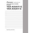
IC152 (pins 2, 5) DDC_RX1
Q
IC101 (pins 58, 59, 62, 63, 66, 67, 70, 71) TMDS_RX2
A
Are signals detected?
No
Check the soldering of CN101. If soldering has not been done correctly, replace CN101.
Do signals (approx. 0.5 Vp-p) run in all the lines?
No
Check the soldering of CN102. If soldering has not been done correctly, replace CN102.
M
Yes
IC152 (pins 3, 6) Are signals the same as those at Pins 2 and 5 detected ? N Yes Q153 (pins 1, 4) Are signals the same as those at Pins No 6 and 3 but whose voltage has been converted from 5V to 3V detected? Yes
R
Yes DDC_RX2 No Check the soldering of CN102. If soldering has not been done correctly, replace CN102.
B
IC172 (pins 2, 5) No Check the soldering of IC152. If soldering has not been done correctly, replace IC152.
Are signals detected?
R
Yes
IC172 (pins 3, 6) Are signals the same as those at Pins 2 and 5 detected ? Check the soldering of IC172. If soldering has not been done correctly, replace IC172.
C
Check the soldering of Q153. If soldering has not been done correctly, replace Q153.
No
S
Yes
O
IC161 (pins 2, 15) Are signals the same as those at Pins 3 and 13 detected immediately after the power is turned on? Yes IC151 (pin 8) No Check the soldering of D151. If soldering has not been done correctly, replace D151.
Q173 (pins 1, 4) Are signals the same as those at Pins 6 and 3 but whose voltage has been converted from 5V to 3V detected? Yes
No
No Check the soldering of IC161. If soldering has not been done correctly, replace IC161.
Check the soldering of Q173. If soldering has not been done correctly, replace Q173.
P
O
IC161 (pins 4, 11)
D
Is the voltage about 5V? Yes
Are signals the same as those at Pins 3 and 13 detected immediately after the power is turned on?
No Check the soldering of IC161. If soldering has not been done correctly, replace IC161.
Check the soldering of IC151. If soldering has not been done correctly, replace IC151.
T
Yes IC171 (pin 8)
Is the voltage about 5V? Yes Replace IC171
No
Check the soldering of D171. If soldering has not been done correctly, replace D171.
E
F
VSX-AX4AVi-S
5 6 7 8
213
|
|
|
> |
|