|
|
|
Who's Online
There currently are 5894 guests online. |
|
Categories
|
|
Information
|
|
Featured Product
|
|
|
 |
|
|
There are currently no product reviews.
 ;
Exactly what was needed to assess the product - excellent value and great service
 ;
Nice to have the service manual for the Sony DCR-TRV345E now. The document is of excellent quality.
;
MACKIE HR824 26 pages English-only Service Manual contains:
1) HR824 technical overview with the description of front and rear panel switches.
2) HR824 specs
3) Block Diagram
4) Wiring Diagram
5) Packaging management
6) Spare part & final assembly list (for PCB rev A and B) + exploded view
7) Test Procedures (where, how to measure voltage...) including Test Point diagram on the PCB.
8) IC and Transistor charts.
Excellent guide: very clear, good scan quality enabling us to print readable diagram :-)
Note:
Mackie HR824 make extensive use of surface mount devices (SMD). Service on the HR824 must
only be undertaken by experienced service technicians with the right tools, experience and patience to perform surface mount rework when needed.
;
This Service manual is very well scanned and its clean to read, no any anti-theft words that un-english could understand. I got my CCD600 working with this manual and it´s clear shematics :)
;
I was very pleased with the service provided and was surprised at how good the quality was of the manual. I thought it may be a third generation copy or so, but it is as good as the websites that charge 3 times this much. I repair some electronics for family and friends without charge, so this is perfect for me. Thank you very much.
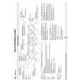
5
6
7
8
C
R452 C414 SY IN VCSDA
A
b-2
Is there a Y signal? Yes C420 SC IN No Diagnose between the BOARD TO BOARD Assy and S. VIDEO Assy.
d-1
Is there a same signal as VCSDA (0 to 3.3 V)? Yes R454 VCSCL No Check the Q451. If Q451 is failure, replace Q451.
b-3
Is there a C signal? Yes No Diagnose between the BOARD TO BOARD Assy and S. VIDEO Assy. Is there a same signal as VCSCL (0 to 3.3 V)? Yes
d-2
No Check the Q451. If Q451 is failure, replace Q451.
B
Note: Check is unnecessary because component input does not convert it.
Step 3-5: VIDEO CLK, DATA
IC701 (Pin 48) LLC1
Step 3-3: Reset
CN318 (Pin 2) XVCRST
e A
Is the voltage "H" (5 V)? No Diagnose between the BOARD TO BOARD Assy and MAIN Assy. Is there a clock (27 MHz)? Yes IC701 (Pins 2 to 9) P8 to P15 No Check the parts and patterns in the path (IC401). If IC401 is failure, replace IC401.
C
X'tal
Yes
f
IC401 (Pin 22) Is there the CLK (28.63636MHz) ? Yes XTAL
c
No Check the X401 or IC402. If X401 or IC402 is failure, replace X401 or IC402.
Is there a data?
No Check the parts and patterns in the path. If IC401 is failure, replace IC401.
Yes
Step 3-6: Video Output
IC701 (Pin 35) DACA
D
Step 3-4: I2C
CN318 (Pin 4) VCSDA
g-1
Is there a composite signal? Yes CN316 (Pin 21) No Check the parts and patterns in the path. If IC701 or R731 or R732 or Q731 is failure, replace it. CVBS OUT
A
Does a signal output in constant period (0 to 5 V) ? Yes CN318 (Pin 3) No Diagnose between the BOARD TO BOARD Assy and MAIN Assy.
a
VCSCL Is there a composite signal? Yes IC701 (Pin 33) DACB No Check the parts and patterns in the path. If Q731 or R733 is failure, replace Q731 or R733. No Diagnose between the BOARD TO BOARD Assy and MAIN Assy.
E
A
Does a clock output in constant period (0 to 5 V) ? Yes
g-2
Is there a Y signal? Yes No Check the parts and patterns in the path. If IC701 or R741 or R742 or Q741 is failure, replace it.
F
D
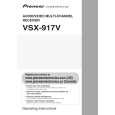
VSX-917V-K
5 6 7 8
115
|
|
|
> |
|