|
|
|
Who's Online
There currently are 6024 guests online. |
|
Categories
|
|
Information
|
|
Featured Product
|
|
|
 |
|
|
There are currently no product reviews.
 ;
This manual was exactly what i needed and could not find elsewhere. Price is not too high. Great !
;
ecelent I was reciver the service manual soon I fell so happy very complete 100% positive all by this store tanks atte Luis salazar
 ;
A great copy of the manual, and the only one I could find anywhere on the net! The circuit diagrams are easily readable, all component values marked and easy to see. A highly appreciated download!
;
Great Manual. This manual is available no where else. It was exactly what I was looking for.
;
The TEAC A-1500's Service Manual was instrumental in reviving this classic reel-to-reel. Not only does it have the schematics, exploded parts diagram and parts list, it also provided mechanical adjustment information that approximate factory default settings.
1
2
3
4
A
A
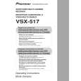
Step 6: DIR
Check that the SPDIF signal is output. Check that changes by pulling out and inserting the digital input lines. IC601 (Pin 1) No Replace IC952. Can No Check the DIGITAL INPUT Assy, observe the digital signal and parts and patterns in the path. ? (0 V � 4 V) Yes IC601 (Pin 5) IN2 (OPT: CD-R/TAPE/MD) IN1 (OPT: TV/SAT)
IC952 (Pin 14)
Do convert 3 V into 5 V for pin 6 input? Yes IC952 (Pin 13)
B
Do convert 3 V into 5 V for pin 7 input? Yes To Step 5
No Replace IC952. Can No Check the DIGITAL INPUT Assy, observe the digital signal and parts and patterns in the path. ? (0 V � 4 V) Yes IC601 (Pin 44) IN3 (COAX: DVD/LD) No Check the parts and patterns in the path. (1.65 V center, amplitude more than 0.2 Vp-p) IN4 (COAX: CD)
Step 5: X'tal
IC802 (Pin 2)
C
Can observe the digital signal ? Yes No Replace IC802 or X801.
Is there a 24.576 MHz output? Yes IC802 (Pin 7)
IC601 (Pin 42) Can observe the digital signal ? Yes
No
Check the parts and patterns in the path.
(1.65 V center, amplitude more than 0.2 Vp-p) Front IN (OPT: VIDEO2)
Is there a 24.576 MHz output? Yes
D
No Check the path to pin 45 of IC801. Replace IC802.
IC601 (Pin 7)
IC802 (Pin 5)
Can observe the No Check the FRONT IN Assy, and digital signal parts and patterns in the path. ? (0 V � 4 V) No Check the path to pin 30 of IC601. Replace IC802. Yes Check that the data and clock signals are output.
Is there a 24.576 MHz output? Yes
IC601 (Pin 27) To Step 6 Is there a master clock output?
E
MCKO2 (Master clock) Is the voltage of PDN IC601-pin 31 5 V?
No
No Check the other assy. (surrounding of the microcomputer) No Replace IC601.
(0 V � 3.3 V) Yes
IC601 (Pin 24)
LRCK (LR clock)
Is there a LR clock output? Yes
F
No Replace IC601. (0 V � 3.3 V)
B
72
1 2
VSX-517-K
3 4
|
|
|
> |
|