|
|
|
Who's Online
There currently are 5711 guests online. |
|
Categories
|
|
Information
|
|
Featured Product
|
|
|
 |
|
|
There are currently no product reviews.
 ;
The manual was complete and extremely helpful in both diagnosing the problem I was having as well as fixing it. Excellent quality. I will getting additional manuals in the future.
;
Exactly the JVC service manual and schematics that I was looking for - delivered just hours after order. Will do business again!
;
This is a fantastic site, ad I have been a returning satisfied cusumer!
Thanx for a great sevice!
;
Je suis audiophile belge, électronicien et créateur d'enceintes acoustiques.
J'ai apprécié la qualité des documents fournis. Ils sont très lisibles, ils peuvent être agrandis sans problème et ils sont complets. Pour moi, c'est parfait. Pour cette qualité, je suis d'accord de payer. Et le système de paiement et d'envoi est simple. Merci, continuez comme cela.
Frédéric
;
The cover page was a little scary, very dark but readable. The remainder of the document was better copy and easily readable. Why would I give 5 Stars? (1) PRICE, (2) AUTHENTICITY, It was the real deal, filled with service information, including the specific information I required. (3) PRIVACY, I didn't start to get slammed with spam. (4) EASY TRANSACTION. Painless. (5) COMPLETE, I have found several manuals here, that I could find nowhere else. (6) I will be a repeat customer!
1
2
3
4
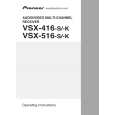
7.3.4.3 Troubleshooting Step 1: Connectors
A
CN701, CN702 Are the connectors securely inserted ? Yes
6
IC703 (pin 1), IC702 (pin 7)
3.3 V Reg. output / 1.8 V Reg. input Is IC703 abnormally hot? Yes No
No Insert the connectors securely.
Is the voltage 3.3 V ? Yes
No
Replace IC703.
To STEP 2 The output and GND may be short-circuited. Check the path between them.
Step 2: Power supply
B
7
IC762 (pins 37, 47) FLASH ROM
1
CN702 (pin 4) Is the voltage 5V? Yes
5 V input Is there any loose connection of CN702? Yes Is the voltage 3.3 V ? Yes Check the MOTHER Assy. No Check the parts and patterns in the path.
No
No
8
IC761 (pins 1,3,9,14,27,43,49) SDRAM
To STEP 1
2
C
IC703 (pin 3)
3.3 V Regulator IC input
Is the voltage 3.3 V ? Yes
No
Check the parts and patterns in the path.
Is the voltage 5V? Yes
No
Check the patterns in the path.
9
IC953 (pin 14) Is the voltage 3.3 V ? Yes
5-3 Converter
No
Check the parts and patterns in the path.
3
IC951 (pin 14)
3-5 Converter
D
Is the voltage 5V? Yes
No
Check the parts and patterns in the path.
10 IC701 (pins 16,33,64,76,112) USB Media control IC
Is the voltage 3.3 V ? Yes
No
Check the parts and patterns in the path.
4
IC771 (pin 5)
USB Power SW
Is the voltage 5V? Yes
E
No
Check the parts and patterns in the path.
11
IC702 (pin 1)
1.8 V Regulator output
5 IC7814 (pins 14, 15) DAC
Is the voltage 5V? Yes No Check the parts and patterns in the path.
Is the voltage 1.8 V ? Yes
No
Is IC702 abnormally hot? Yes
No
Replace IC702.
The output and GND may be short-circuited. Check the path between them.
A
F
116
1 2
VSX-516-K
3 4
|
|
|
> |
|