|
|
|
Who's Online
There currently are 5857 guests online. |
|
Categories
|
|
Information
|
|
Featured Product
|
|
|
 |
|
|
There are currently no product reviews.
 ;
A great copy of the manual, and the only one I could find anywhere on the net! The circuit diagrams are easily readable, all component values marked and easy to see. A highly appreciated download!
 ;
Great Manual. This manual is available no where else. It was exactly what I was looking for.
;
The TEAC A-1500's Service Manual was instrumental in reviving this classic reel-to-reel. Not only does it have the schematics, exploded parts diagram and parts list, it also provided mechanical adjustment information that approximate factory default settings.
;
This service manual was determinant to enable to fix my Alpine Amplifier. I am pleased with my purchase. For a 5 star rating I would like to see a higher resolution scan of the printed circuit board lay-out because the gray scale grafics was dificult to see. Also some schematic diagrams were scanned at a slight angle. Never the less, it had all information I needed to troubleshoot and service my equipment.
;
Complete manual, the good quality of reproduction allows enlarged print-out of the schematic diagram in the size it probably had in the original print edition and which is necessary for practical use.
Front
Surround
Subwoofer
Center
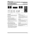
RRV3554
S-FCRW2900-K
ORDER NO.
SPEAKER SYSTEM
S-FCRW2900-K
XTWUC
1. REASSEMBLY AND DISASSEMBLY PRECAUTIONS
1.1 FRONT/SURROUND SPEAKER
The grille is attached to the cabinet by 6 external screws. To detach it, unfasten those screws. The speaker unit, together with the grille, is attached to the cabinet by 4 external screws. To detach it, first unfasten those screws. Next remove the cabinet. Then removethe cable. When attaching it, face its terminal downward. The speaker unit, together with the grille assy, is attached to the cabinet by 4 external screws. To detach it, first remove the grille assy. Next remove the cabinet. Then removethe cable. When attaching it, face its terminal toward the input terminal.
1.3 SUBWOOFER
The speaker unit is attached to the back board by 4 external screws. To detach it, unfasten those screws. When attaching it, face its terminal downward. The cosmetic baffle assy is attached to the baffle board by press-fitting. To detach it, pry it open by inserting a flat blade screwdriver into lower slot.
1.2 CENTER SPEAKER
The grille assy is attached to the cabinet by 8 external screws. To detach it, unfasten those screws.
PIONEER CORPORATION
4-1, Meguro 1-chome, Meguro-ku, Tokyo 153-8654, Japan PIONEER ELECTRONICS (USA) INC. P.O. Box 1760, Long Beach, CA 90801-1760, U.S.A. PIONEER EUROPE NV Haven 1087, Keetberglaan 1, 9120 Melsele, Belgium PIONEER ELECTRONICS ASIACENTRE PTE. LTD. 253 Alexandra Road, #04-01, Singapore 159936
PIONEER CORPORATION 2007
T-ZZR APR. 2007 Printed in Japan
|
|
|
> |
|