|
|
|
Who's Online
There currently are 5682 guests online. |
|
Categories
|
|
Information
|
|
Featured Product
|
|
|
 |
|
|
There are currently no product reviews.
 ;
I was at first dubious about payiong for downloaded manuals but having done so, I was extremely impressed with quality of the two manual I ordered, well worth the small price I paid.
I would highly recommend these to my friends.
;
reasonable price for the schematic - the service is perfect, all as expected and pointed by instructions - good scan of the original plans - thank you!
;
Manual was just as described!!! I odered it and in less than a day was able to download it and the text was clear and pages were all complete just as the original manual was. Purcashed this for a friend and they were more than happy. Perfect all around!
 ;
Excellent service and prompt delivery. But it's not a manual - only 4 pages wiring diagrams.
Thanks.
;
The manual I purchased was exactly what I needed to repair my Toshica television. The manual contained schematics and troubleshooting information that was very helpful.
5
6
7
8
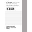
8. PANEL FACILITIES
1 Power indicator (STANDBY/ON)
A
FRONT PANEL 1
ST ANDBY/ON POWER
VOLUME
MIN
MAX
2 3
Lights green when the power has been switched ON. Lights green when the speakers receive an audio signal. If the power is switched OFF only briefly, the indicator lights green when power is restored. If no signal is present for more than 8 minutes, the subwoofer automatically reverts to standby mode and the power indicator lights red. If, subsequently, a signal is received, power automatically comes back on and the power indicator lights green.
POWERED SUB WOOFER
2 POWER switch
Pressing once switches the unit ON. Press again to switch OFF. NOTE: If you are planning on switching the unit OFF for a long period of time, make sure to check that the indicator light has gone out after switching OFF.
B
3 Volume knob (LEVEL)
� � Sets the subwoofer volume. Turn the knob slowly from the MIN position. With this unit, the bass level can be independently set, so do not turn up the bass on the stereo amplifier.
REAR PANEL 4
LINE LEVEL INPUT
LINE VOLTAGE SELECTOR SWITCH
4 Line Level Input terminal (LINE LEVEL INPUT)
240V
220- 110230V 127V
Connects to the stereo amplifier�s SUBWOOFER PREOUT terminal, with the specially provided RCA plug cord. When depressed (180°), the output phase becomes the reverse of the input signal, and when raised (0 °), it is in the same phase as the input signal.
C
AC IN
7
5 Phase switch (PHASE 0 °/180 °)
5 6
PHASE 180° 0° AUTO ST ANDBY ON OFF
� Normally, the switch is set to ( 0 ° ). But when the sound connection between the subwoofer and the left and right speakers sounds unnatural, tyr switching to 180 ° and set the switch in the position where the sound is natural.
6 Auto Standby switch (AUTO STANDBY)
Switches the Auto Standby feature on/off. Auto Standby When switched ON (the default setting is OFF ), the Auto Standby feature becomes active. In this mode, if there is no input signal for eight minutes the system automatically switches to standby. The power is automatically switched on again if an input signal is detected.
D
7 AC INLET
240V 220230V 110127V
� Connect the power cord to the powered subwoofer unit�s AC INLET.
AC IN
E
� Connect the power cord to a AC socket.
NOTE � There may be cases where a connected component outputs noise or some other non-audio signal which causes this system to automatically power on when in Auto Standby mode. If this happens, switch off the Auto Standby mode and switch the system on/off manually.
F
S-EW5
5 6 7 8
41
|
|
|
> |
|