|
|
|
Who's Online
There currently are 5998 guests online. |
|
Categories
|
|
Information
|
|
Featured Product
|
|
|
 |
|
|
There are currently no product reviews.
 ;
Thank you for your shop manual! Your help was very useful - the device is repaired! Once again - Thank you! I wish you a successful business! Edward (Russia).
;
It was a great experience,instead of purchasing a new Stereo Amplifier ,in just minutes i repaired my old one and that was thaks to the manual I have purchased from you.
Thanks again.
Samuel Alter
;
Das ging ja sehr unkompliziert hat bestens geklappt und die Quallität ist auch noch gut.
Vielen Dank dafür.
;
Everything okay, thanks a lot. It was a pleasure for me to make a deal with you.
;
A deal without problems, very fast and the manual is a good quality. Sorry for the my english.
5
6
7
8
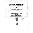
7. GENERAL INFORMATION
7.1 DISASSEMBLY
Removing the Amplifier Module
1 ) Reverse the cabinet and remove the Rubber Pad (4pcs.). Unfasten 4 screws attaching the Reflective Board. 2 ) Unfasten 4 screws attaching the Speaker. Disconnect the Speaker Cord from the Speaker. 3 ) Remove the Amp Box Press Board. 4 ) Loosen the cables styling in the cabinet 5 ) Unfasten 6 screws attaching Front Panel. Next disconnect Jumper Read(9P) from FRONT ASSY. 6 ) Unfasten 16 screws attaching the Amp Box L and S. 7 ) Pull out the Amp Box from the cabinet and insert a hand to the frame which attached the Amp Box Press Board, and disconnect the Connector from the Amplifier Module. The Connector which needs to be disconnect: All the Connectors from the Transformer The Connector(2P) from the Front Panel Assy
Removing the Speaker
1 ) The Speaker is attached to the bottom board by 4 external screws. To detach it, first remove the Rubber Pad(4 pcs.) and Reflective Board. Next unfasten those screws. 2 ) When attaching the Speaker, it attaches according to direction of a photograph (lower left figure).
A
Removing the Front Panel Assy (FRONT, LED, SW ASSYS)
1 ) Before removing the Front Panel Assy, first remove the Speaker and loosen the Jumper Read(9P) styling. 2 ) The FRONT, LED and SW ASSYS are attached to the Front Panel. The Front Panel is attached to the cabinet by 6 external screws. To detach it, unfasten those screws. 3 ) Disconnect the Jumper Read(9P). 4 ) Disconnect the Connecting Cord(2P) from Rear Panel of Amplifier Modure. It is able to detach the Front Panel Assy. 5 ) The FRONT ASSY is attached to the Inner Panel. When removing the Inner Panel, first remove the Volume Knob. And then unfasten 5 screws of the Front Panel rear side. The Nut for Volume is locked by adhesives. When attaching the FRONT ASSY again, lock of the Nut is needed. (refer to 37-38 pages) 6 ) The SW ASSY is attached to the Inner Panel. After detaching the Inner Panel, Back Cover and Power Button, it is able to detach the SW ASSY. 7 ) After detaching the Inner Panel, it is able to detach the LED ASSY. 8 ) When attaching the Volume Knob again, push the C RING until it reaches the rib of the Volume Knob. C RING
B
Note 1: The Connector has a stopper. When disconnecting, it unplugs with grasping a stopper.
C
Stopper
8 ) Pull out the Amplifier Module. Go to " Removing the Amplifier Module Assys" next page.
D
Removing the Power Transformer
1 ) The Transformer is attached to the Transformer Attachment Board by 4 screws. The head of Screws are locked by adhesives. 2 ) The Transformer Attachment Board is attached to Back Board by 4 external screws. The Screws are locked by adhesives. When detaching the Transformer, first remove the Speaker and the Amplifire module. And then, unfasten those screws. 3 ) When attaching the Transformer to the Transformer Attachment Board and the Transformer Attachment Board to Back Board again, lock of the Screws are needed. (refer to 37-38 pages)
E
Note : This photograph may show a different model. However, the method for disassembly is the same.
F
S-EW5
5 6 7 8
35
|
|
|
> |
|