|
|
|
Who's Online
There currently are 6043 guests online. |
|
Categories
|
|
Information
|
|
Featured Product
|
|
|
 |
|
|
There are currently no product reviews.
 ;
I am a vintage hifi collector. No way to fix that device without the appropriate service manual...thanks to your site I got it and every thing is easier now. I got the manual right after ordering: fast cheap accurate ... thank you
;
Wonderful job clear. Qick fantastic. These people are really good. If even a problem arise they are wonderful assisting you. These scheme is so net despite this is a very old TV. Thank you for everything!!!!!!!!
;
Detailed schematic diagram, manual for professionals
;
Good service manual,exploded view,adjusment and test point locations,head alignment,mechanical checks and adjusments,all perfect.
;
Block diagram,play rec block diagram,adjusments, it's a very good well done repair manual.
1
2
3
4
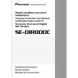
7.1.2 Disassembly 7 Transmitter
A
1. Remove the two screws of the stand. 2. Remove the four screws of the lower case. 3. Slide the cover of the upper and lower cases. 4. Remove the lower case. 5. Remove the soldering from the charge terminal. 6. Remove the three fixing screws of the phono jack. 7. Remove the Board Assy from the upper case with the VR control attached.
B
Board Assy
7 Headphones
C
<L side> 1. Remove the ear pad. 2. Remove the three screws of the base and remove the base. 3. Remove the two screws of the base cover and remove the base cover. 4. Remove the soldering from the lead wire on the photo board. 5. Remove the screw of the board.
POWER BOARD Assy
6. Remove the photo cover.
D
PHOTO BOARD Assy
<R side> 1. Remove the ear pad. 2. Remove the three screws of the base and remove the base. 3. Remove the two screws of the base cover and remove the base cover. 4. Remove the soldering from the lead wire on the photo board. 5. Remove the screw of the board.
E
MAIN BOARD Assy
6. Remove the photo cover.
PHOTO BOARD Assy
F
32
1 2
SE-DIR800C
3 4
|
|
|
> |
|