|
|
|
Who's Online
There currently are 6017 guests online. |
|
Categories
|
|
Information
|
|
Featured Product
|
|
|
 |
|
|
There are currently no product reviews.
 ;
Great Manual! It contains all the wiring schematics and mechanical exploded views that are essential for service and repair. I was surprised I even found this for such an old machine. Only wish I knew of this site many years ago.
;
Great manual very clear copied. You are making an incredible job. I appreciate a lot the rapidity and your efficiency. Thanks a lot
;
Good pdf of the service manual for this unit. Includes disassembly instructions, full schematics, board layouts, parts lists and diagnostic information. Some information is in the pdf twice (single pages, and split pages), but that could be how it was originally generated by panasonic, or perhaps the idea is to make it eaiser to put onto 8.5 x 11" pages.
Information was exactly what I needed. Delivery was overnight (less than 12 hours) and I was happy with the process.
;
5 STARS for FAST DELIVERY, BEST PRICES and QUALITY PRODUCT. Item was exactly as described with superb resolution. Will definitely source all my future requirements from this website. Thanks a lot owner-manual.com!
;
OEM manual provided all schematics, board layouts and component specs necessary to facilitate unit maintenance. All pages were clear and readable.
1
2
3
4
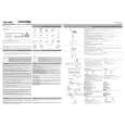
S-DV55SW-K, S-DV55SW-Q
3. PCB CONNECTION DIAGRAM
3.1 AF ASSY
A
NOTE FOR PCB DIAGRAMS :
1. Part numbers in PCB diagrams match those in the schematic diagrams. 2. A comparison between the main parts of PCB and schematic diagrams is shown below.
Symbol In PCB Diagrams Symbol In Schematic Diagrams B CEB CE Part Name
A AF ASSY
To Power Transformer
B CN3302
BCE B BCE D DGS GSD GS C EB C E
Transistor
Transistor with resistor
Field effect transistor
Resistor array
B
3-terminal regulator
3. The parts mounted on this PCB include all necessary parts for several destinations. For further information for respective destinations, be sure to check with the schematic diagram. 4. View point of PCB diagrams.
Connector
Capacitor
SIDE A
P.C.Board
C
Chip Part
SIDE B
IC13 IC14 IC15 IC12 IC11
IC16
Q61
D
16
A
1 2 3 4
|
|
|
> |
|