This service Manual for my JVC AV29BF10EES is very helful. Everything is show in detailed diagrams!!!! If you need really good source of information for this type JVC you are on the right place. I am satisfied and very glad for this excellent book. Thank you.
Great service, great value like always!!!
Some of the writing is a bit blur but all is usable.
A+++++++++++++++++
Text excerpt from page 21 (click to view)
1
2
3
4
SD-T50W1
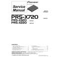
3. PCB CONNECTION DIAGRAM
To POWER SUPPLY ASSY J101 E14
NOTE FOR PCB DIAGRAMS:
1. Part numbers in PCB diagrams match those in the schematic diagrams. 2. A comparison between the main parts of PCB and schematic diagrams is shown below.
Symbol in PCB Diagrams Symbol in Schematic Diagrams Part Name
A
To T1 POWER TRANSFORMER
Symbol in PCB Diagrams
Symbol in Schematic Diagrams
Part Name
3-terminal regulator 3. The parts mounted on this PCB include all necessary parts
B BCE B BCE
C
EB
C
E Transistor
for several destination. For further information for respective destinations, be sure to check with the schematic diagram.