|
|
|
Who's Online
There currently are 6043 guests online. |
|
Categories
|
|
Information
|
|
Featured Product
|
|
|
 |
|
|
There are currently no product reviews.
 ;
Very good reproduction (copy) of original manual. Didn't have a parts list, but schematic was completely labeled with parts. Complete instructions on how to adjust mechanical functions of the 8-track deck. Well worth having and at a very reasonable cost.
;
It's a full manual. All the parts are in there. I haven't found the problem yett, but I am working on it; hope I can rebuild the part myself. To make it more secure and unbreakable this time. Because the part has failed several times before and costs a lot to let it be repaired.
Thanks so much for this rich illustrated and parted manual.
;
I downloaded the document. The manual was complete, well scanned and everything was legible. I could zoom in see what I needed to know. There's not much more that you can ask.
;
It was complete service manual with all needed service informations. Thanks.
 ;
El manual esta muy detallado, los numeros de partes y los esquemas de despiece son correctísimos y muy claros, tanto para los técnicos experimentados como para los novatos.
1
2
3
4
1.3 NETWORK ASSY
A
Before removing the Network Assy, remove the grille and each speaker unit then disconnect the cords from the speaker unit.
� For removal/reattachment of the Network Assy for the woofer: Only the woofer must be removed beforehand. � For removal/reattachment of the Network Assy for the midrange unit and the tweeter: Removal of all the units is required.
[1] Network Assy for the Woofer
� The Network Assy for the woofer is located inside the left panel behind the woofer and secured with four screws.
(1) Remove the acoustic absorbent pads that are located near the input terminals. (2) Remove the two nuts that secure the round connectors from the lower input terminals. (See Fig. 2-1. Tool: Box wrench, 14 mm/GGH-002) (3) Remove the four screws that secure the Network Assy then pull the Assy out through the hole where the woofer was attached. (See Fig. 2-2.) (4) When reattaching, pass the Network Assy through the hole where the woofer was attached then secure it in place with the four screws. (See Fig. 2-2.) (5) Among the two pairs of cords from the Network Assy, connect the cords with the round connectors to the lower input terminals and secure them with the nuts. (See Fig. 2-1. Tool: Box wrench, 14 mm/GGH-002) (6) Apply adhesive to the secured nuts. (Adhesive: DIABOND black/GYL-014) (7) Reinstall the acoustic absorbent pads near the input terminals. (8) Connect and solder the remaining pair of cords from the Network Assy to the woofer and reinstall the woofer in the cabinet.
[2] Network Assy for the midrange unit and the tweeter
� The Network Assy for the midrange unit and the tweeter is located inside the right panel behind the woofer and attached with four screws.
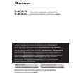
(1) Remove the acoustic absorbent pads that are located near the input terminals, inside and at the rear of the chamber, and behind the chamber. (2) Remove the two nuts that secure the round connectors from the upper input terminals. (See Fig. 2-1. Tool: Box wrench, 14 mm/GGH-002) (3) Remove the four screws that secure the closure panel inside the chamber, remove the four screws that secure the Network Assy, and pull the Network Assy out through the hole where the woofer was attached. (See Figs. 2-3 and 2-4. Tool: Screwdriver/GGK1012) (4) When reattaching, pass the Network Assy through the hole where the woofer was attached and secure it in place, using the four screws.(See Fig. 2-3. Tool: Screwdriver/GGK1012) (5) Among the cords from the Network Assy, connect the cords with the round connectors to the upper input terminals and secure them with the nuts. (See Fig. 2-1. Tool: Box wrench, 14 mm/GGH-002) (6) Apply adhesive to the secured nuts. (Adhesive: DIABOND black/GYL-014) (7) Pass the closure panel and the two pairs of cords from it through behind the chamber then secure the closure panel from inside the chamber, using the four screws. (See Fig. 2-4.) (8) Reinstall the acoustic absorbent pads near the input terminals, inside and at the rear of the chamber, and behind the chamber. (9) Connect and solder the cords to the CST-unit speaker and reinstall it in the cabinet.
Note: The NW Assy shown in this photo is for the S-1EX, but the shape of the closure panel is the same.
B
C
D : White with Black line Apply adhesive. : White Apply adhesive. Be sure to apply adhesive only to the head of a screw, but not around the nut.
From the Network Assy for the midrange/tweeter From the Network Assy for the woofer Fig. 2-1: Input terminals (inside the cabinet) E Front side
Upper side
Closure panel : Screws
Chamber F : Screws Fig. 2-2: Specifications for attaching the Network Assy for the woofer Bottom side : Screws Fig. 2-3: Specifications for attaching the Network Assy for the midrange/tweeter Fig. 2-4: Specifications for attaching the closure panel (cross-sectional view of the CST unit speaker)
4
1 2
S-4EX-W
3 4
|
|
|
> |
|