|
|
|
Who's Online
There currently are 6043 guests online. |
|
Categories
|
|
Information
|
|
Featured Product
|
|
|
 |
|
|
There are currently no product reviews.
 ;
Wonderful job clear. Qick fantastic. These people are really good. If even a problem arise they are wonderful assisting you. These scheme is so net despite this is a very old TV. Thank you for everything!!!!!!!!
;
Detailed schematic diagram, manual for professionals
;
Good service manual,exploded view,adjusment and test point locations,head alignment,mechanical checks and adjusments,all perfect.
;
Block diagram,play rec block diagram,adjusments, it's a very good well done repair manual.
;
Very clear copy of the philips service manual. Fast delivery. Thank you very much
1
2
3
4
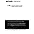
2.3 NETWORK ASSY
Before removing the Network Assy, remove the grille and each speaker unit then disconnect the cords from the speaker unit. � For removal/reattachment of the Network Assy for the woofer: Only the woofer must be removed. � For removal/reattachment of the Network Assy for the midrange/tweeter: Removal of all the units is required.
A
2.3.1 Network Assy for the Woofers
� The Network Assy for the woofers is located inside the back board behind the lower woofer and secured with 4 screws. (1) Remove the acoustic absorbent pads at the input terminals. (See Figs. 2-5 to 2-8.) (2) Remove the 2 nuts that secure the round connectors from the lower input terminals. (See Fig. 2-1. Tool: Box wrench, 14 mm/GGH-002) (3) Remove the 4 screws that secure the Network Assy then pull the Assy out through the hole where the woofer was attached. (See Fig. 2-2.) (4) When reattaching, pass the Network Assy through the hole where the lower woofer was attached then secure it in place with the 4 screws. (See Fig. 2-2.) (5) Among the 3 pairs of cords from the Network Assy, connect the cords with black tape to the lower input terminals and secure them with the nuts. (See Fig. 2-1. Tool: Box wrench, 14 mm/GGH-002) (6) Apply adhesive to the secured nuts. (Adhesive: DIABOND black/GYL-014) (7) Reinstall the acoustic absorbent pads at the input terminals. (See Figs. 2-5 to 2-8.) (8) Among the 3 pairs of cords from the Network Assy, connect and solder the remaining 2 pairs of cords with white tape to the woofer and reattach the woofer in the cabinet.
2.3.2 Network Assy for the midrange / tweeter
� The Network Assy for the midrange/tweeter is attached to the inside of the left side board behind the upper woofer, using 4 screws. (1) Remove the acoustic absorbent pads at the input terminals, inside and at the rear of the chamber, and behind the chamber. (See Figs. 2-5 to 2-8 and 2-9 to 2-11.) (2) Remove the 2 nuts that secure the round connectors from the upper input terminals. (See Fig. 2-1. Tool: Box wrench, 14 mm/GGH-002) (3) Remove the 4 screws that secure the closure panel inside the chamber, remove the 4 screws that secure the Network Assy, and pull the Network Assy out through the hole where the woofer was attached. (See Figs. 2-3 and 2-4. Tool: Screwdriver/GGK1012) (4) When reattaching, pass the Network Assy through the hole where the upper woofer was attached and secure it in place using the 4 screws. (See Fig. 2-3. Tool: Screwdriver/GGK1012) (5) Among the cords from the Network Assy, connect the cords with the round connectors to the upper input terminals and secure them with the nuts. (See Fig. 2-1. Tool: Box wrench, 14 mm/GGH-002) (6) Apply adhesive to the secured nuts. (Adhesive: DIABOND black/GYL-014) (7) Pass the 2 pairs of cords from the closure panel through behind the chamber then secure the closure panel from inside the chamber, using the 4 screws. (See Fig. 2-4.) (8) Reinstall the acoustic absorbent pads at the input terminals, inside and rear of the chamber, and behind the chamber. (See Figs. 2-5 to 2-8 and 2-9 to 2-11.) (9) Connect and solder the cords to the coaxial-unit speaker and reattach it in the cabinet.
B
C
Apply adhesive. +: White with Black line
From the Network Assy for the midrange/tweeter From the Network Assy for the woofers
-: White Apply adhesive.
D
Fig. 2-1: Input terminals (inside the cabinet) Upper side Upper side
E
Closure panel : Screws
Bottom side Bottom side : Screws Fig. 2-2: Specifications for attaching the Network Assy for the woofers : Screws Fig. 2-3: Specifications for attaching the Network Assy for the midrange/tweeter
Chamber Fig. 2-4: Specifications for attaching the closure panel (cross-sectional view of the coaxial-unit speaker)
F
S-1EX
1 2 3 4
9
|
|
|
> |
|