|
|
|
Who's Online
There currently are 6043 guests online. |
|
Categories
|
|
Information
|
|
Featured Product
|
|
|
 |
|
|
There are currently no product reviews.
 ;
Full Panasonic service Manual, as described, no problems
;
This place is amazing. Got our manual in a few hours. Print quality is excellent. Even the manufacturer didn't have this manual. The price was excellent. How many more stars can I give them? More than satisfied.
;
This was a very hard to find manual. The unit is long discontinued and Pioneer doesn't retain every manual for every model. Thanks owner's-manual.com!
 ;
I'm so glad I was able to find a site to download my missing manuals. Very reasonable prices and they kept me informed about the process and I had my manual within less than a day. The only thing I wish was an option is a 100% English version with no spanish or anything. But overall great site.
;
The manual is complete with excellent quality! One suggestion, show number of pages and weather it is multi-lingual. The AD 600 Manuel is about 76 pages and over half is non English. This results in a larger print job than usually needed. Having this information, one could select the desired pages for printing.
Connecting the Unit
Connecting the Speaker Wires
<ENGLISH>
Installation
CAUTION
� Do not install the amplifier on unstable places such as the spare tire board. � The best location for installation differs with the car model and installation location. Secure the amplifier at a sufficiently rigid location. � Make temporary connections first and check that the amplifier and the system operate properly. � After installing the amplifier, confirm that the spare tire, jack and tools can be easily removed.
<ENGLISH>
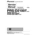
Example of installation on the floor mat or on the chassis
1. Place the amplifier where it is to be installed. Insert the supplied tapping screws (4 � 18 mm) into the screw holes. Push on the screws with a screwdriver so they make marks where the installation holes are to be located. 2. Drill 2.5 mm diameter holes at the point marked, and install the amplifier, either on the carpet or directly to the chassis.
Specifications
<ENGLISH>
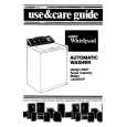
The speaker output mode can be two-channel (stereo) or one-channel (mono). Connect the speaker leads to suit the mode according to the figures shown below.
� Do not connect both the RCA input and the speaker input at the same time.
Two-channel (stereo)
(Right) Speaker (Left)
One-channel (mono)
� Do not install in: �Places where it could injure the driver or passengers if the vehicle stops suddenly. �Places where it may interfere with the driver, such as on the floor in front of the driver�s seat. � Make sure that wires are not caught in the sliding mechanism of the seats, resulting in a short-circuit. � Confirm that no parts are behind the panel when drilling a hole for installation of the amplifier. Protect all cables and important equipment such as fuel lines, brake lines and electrical wiring from damage. � Install tapping screws in such a way that the screw tip does not touch any wire. This is important to prevent wires from being cut by vibration of the car, which can result in fire. � DO NOT allow amplifier to come into contact with liquids due to, for example, the location where the amplifier is installed. Electrical shock could result. Also, amplifier and speaker damage, smoke, and overheating could result from contact with liquids. In addition, the amplifier surface and the surface of any attached speakers could become hot to the touch and minor burns could result. � To ensure proper installation, use the supplied parts in the manner specified. If any parts other than the supplied ones are used, they may damage internal parts of the amplifier, or they may become loose causing the amplifier to shut down. � Never replace the fuse with one of greater value or rating than the original fuse. Use of an improper fuse could result in overheating and smoke and could cause damage to the product and injury including burns.
Power source ........................................................................................................ 14.4 V DC (10.8 V to 15.1 V allowable) Grounding system .......................................................................................................................................... Negative type Current consumption ...................................................................................................... 25 A (at continuous power, 4 �) Average current drawn* .......................................................................................................... 8 A (4 � for two channels) 17 A (4 � for one channel) 17 A (2 � for two channel) Fuse ........................................................................................................................................................................ 30 A � 2 Dimensions .................................................................................................................... 304 (W) � 56 (H) � 195 (D) mm Weight .................................................................................................................... 2.9 kg (Leads for wiring not included) Maximum power output .......................................................................................... 300 W � 2 (4 �) / 1 200 W � 1 (4 �) Continuous power output ........................................................ 150 W � 2 (at 14.4 V, 4 �, 20 Hz to 20 kHz 1.0% THD) 600 W � 1 (at 14.4 V, 4 �, 1 kHz 1.0% THD) 300 W � 2 (at 14.4 V, 2 �, 1 kHz 1.0% THD) Load impedance ...................................................................................................................... 4 � (2 � to 8 � allowable) (Bridge connection: 4 � to 8 � allowable) Frequency response ........................................................................................................ 10 Hz to 50 kHz (+0 dB, �3 dB) Signal-to-noise ratio .................................................................................................................... 100 dB (IEC-A network) Distortion ........................................................................................................................................ 0.005 % (10 W, 1 kHz) Separation .................................................................................................................................................... 70 dB (1 kHz) 60 dB (100 Hz to 10 kHz) Low pass filter ............................................................................................................ Cut off frequency: 40 Hz to 500 Hz Cut off slope: �12 dB/oct High pass filter .......................................................................................................... Cut off frequency: 40 Hz to 500 Hz Cut off slope: �12 dB/oct Bass boost ................................................................................................................................................ Frequency: 50 Hz Level: 0, 6, 9, 12 dB Gain control .................................................................................................................................... RCA: 400 mV to 6.5 V Speaker: 1.6 V to 26 V Maximum input level / impedance .................................................................................................... RCA: 6.5 V / 22 k� Speaker: 26 V / 90 k�
Replacing the terminal cover
1. Align the unit and terminal cover, and insert the screw. 2. Tighten the screw with a 4 mm hexagonal wrench.
Screw Tapping-screws (4 � 18 mm)
Note:
Terminal Cover � Specifications and the design are subject to possible modification without notice due to improvements.
*Average current drawn
� The average current drawn is nearly the maximum current drawn by this unit when an audio signal is input. Use this value when working out total current drawn by multiple power amplifiers.
Speaker (Mono)
CAUTION: To prevent malfunction and/or injury
� To ensure proper heat dissipation of the amplifier, be sure of the following during installation. �Allow adequate space above the amplifier for proper ventilation. �Do not cover the amplifier with a floor mat or carpet. � DO NOT allow amplifier to come into contact with liquids due to, for example, the location where the amplifier is installed. Electrical shock could result. Also, amplifier and speaker damage, smoke, and overheating could result from contact with liquids. In addition, the amplifier surface and the surface of any attached speakers could become hot to the touch and minor burns could result. Floor mat or chassis
Drill a 2.5 mm diameter hole
|
|
|
> |
|