|
|
|
Who's Online
There currently are 6043 guests online. |
|
Categories
|
|
Information
|
|
Featured Product
|
|
|
 |
|
|
There are currently no product reviews.
 ;
El producto satisface las necesidades del servicio t
;
This is a good quality scan of the Operation & Maintenance (Service) Manual for the PAL version of this high-band broadcast umatic, BVU-800P
All schematics and lineup procedures appear to be included in this one manual AFAICT.
The file size is just over 113 MB which gives an idea of the quality and number of pages.
All of the schematics, which contain some fairly small print, are easily readable when you zoom into the page.
John Thompson, Newcastle Upon Tyne, England.
;
Good quality, all schematics of few of models. There is also short form of user manual and regulation manual.
;
Perfect copy of the service manual. you can enlarge every page, and it comes up
with all details.
;
It´s very very nice manual with all, what i need. Original in good quality. Very fast business. Very much thanks...
5
6
7
8
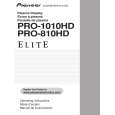
4 X CONNECTOR A Assy, B Assy, 50 SCAN A Assy and B Assy
X CONNECTOR A and B Assy
A
1
Remove the enclosure sheet 1. 50 X DRIVE Assy
Note: Enclosure sheet 1 is attached to comply with the safety standards. Make sure that it will not be shifted or peeled off. If it is peeled off, securely reattach it in its original place.
6
6
6
Remove the one screw. Note: Be sure to remove this screw. If you don't, the connector on the LED Assy may be damaged.
2 3 4 5 6
Remove the jumper wire by removing the flat clamp. Remove the one nyron rivet.
6 2
Flat clamp Enclosure sheet 1
Front chassis VR (50M)
1
3 5
6
B
4
LED Assy
Remove the LED Assy. Remove the front chassis VR (50M) by removing the five screws.
7 8
Remove the eight screws. Remove the X CONNECTOR A and B Assy.
7
50 X DRIVE Assy
�4
7
�4
Note when reassembling the front chassis VR (50M) Remove or loosen the screws that secure the panel holder in order not to damage the front protect panel Assy.
C
8
X CONNECTOR B Assy
8
X CONNECTOR A Assy
50 SCAN A and B Assy
5 5
50 Y DRIVE Assy SCAN heatsink
1 2 3 4 5
Remove the one nylon rivet. Remove the jumper wire by removing the flat clamp. Remove the one screw. Remove the front chassis VL (50M) by removing the five screws. Remove the SCAN heatsink by removing the two screws.
4
4
4
D
4
Front chassis VL (50M)
Flat clamp
2
4
3 6 7 8 9
Remove the ten screws. Disconnect the two pin connectors. Remove the two spacers. Remove the 50 SCAN A and B Assy. 50 Y DRIVE Assy
1
E
6
7
6 8
�3
66
6 8
�3
7
6
Note when reassembling the front chassis VL (50M) Remove or loosen the screws that secure the panel holder in order not to damage the front protect panel Assy.
9
50 SCAN B Assy
9
50 SCAN A Assy
F
PRO-1010HD
5 6 7 8
147
|
|
|
> |
|