|
|
|
Who's Online
There currently are 5979 guests online. |
|
Categories
|
|
Information
|
|
Featured Product
|
|
|
 |
|
|
There are currently no product reviews.
 ;
Good quality, the manual help me to repair the echo/reverb section
;
A good service manual with lots of info and a very fair price
;
Great value, good scan, just as expected, everything that you need.
;
Good scan, great price, but almost the same with the SV260 service manual.
;
This PDF is very comprehensive. It includes drawings, parts lists, schematics, pictures, PCB drawings, mechanical layouts, etc. for all three stackable equipment. The scans are good too. Easy to read and no smudges or black lines. I have no complaints. I will make this site my first stop for finding my service manuals.
PRO-700HD
10 -4
Red line adjustment
1st FAC
� Adjustment in the vertical direction
Start ¶ Vertical correction adjustment of the red line
� Select the Adjustment item
RV - STATIC
1
CH
� Adjust the Data value
2 5 8 0 3 6 9
VOL
or
4 7
or
In particular, be aware of the setting before adjustment.
Note : � Repeat the adjustments until you attain the optimum state. � Fine-adjust over the entire picture to obtain the optimum picture. � If the adjustment of V-STATIC is not possible within the range of 010 to �010, set the data value to 0, turn the centering magnet of the deflection yoke and fine-adjust V-STATIC. Adjustment Method
Adjustment Item 1 2 3 4 5 6 7 RV-STATIC RV-SKEW RV-BOW RV-3D SKEW RV-4D BOW (RV-5D SKEW) (RV-6D BOW)
� � � � � � � � � � � � �
Screen No.
1 2 5 3 6 4 7 8 q 9 w p e
� Adjust the red center to match the green center.
� Adjust so that the red horizontal line at the center overlaps with the green horizontal line.
Note: Do not adjust items 6 to 7.
1 2 3 Line-interval Center-line Adjustment 4 5 6
RV-SIZE RV-LIN RV-MID SIZE RV-MID LIN (RV-5D SKEW) (RV-6D LIN)
� Adjust the interval at the center of the red vertical line to the interval of the green vertical line.
Note: Do not adjust items 5 and 6.
7 Screen
� STATIC
1
Key No.
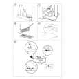
¶Screen�s changes in the vertical direction when manual convergence adjustment is mode The changes at the arrow parts shown below are those implemented using the Volume ª key. Changes are opposite to the arrow when the Volume · key is used.
`
� SKEW
2
� 3D SKEW
3
� 5D SKEW
4
Key No.
� SIZE
8
� MID SIZE
9
� 5D SIZE
10
Key No.
1
� BOW
8
5
� 4D BOW
6
� 6D BOW
7
Key No.
� LIN
11
� MID LIN
12
� 6D LIN
13
Key No.
2
= Fixed position
7
Fig. 7. Vertical correction (1)
198
|
|
|
> |
|