|
|
|
Who's Online
There currently are 5860 guests online. |
|
Categories
|
|
Information
|
|
Featured Product
|
|
|
 |
|
|
There are currently no product reviews.
 ;
I work at an authorized service center and I can tell if a manual is as it should be. This one is. It may be a scan, but a very good one at that. The interesting part for me was the curcuit diagram which was scanned at high quality, making it as good as the original. I will definitely be back as a customer. I need not say this, but I will: the price was the best. Thank you owner-manuals.com .
 ;
really a very good manual even sometimes the quality is no so good as before still very readible and very very useful!
;
FAST very good and clear a great unexpensive job!!! very recomended for all people who are preofessional or hobbists as me!!!!!!
;
Thank you very much for this Service Manual, it helped us a lot to repair the M-4318!
...BUT: The parts list is missing and the free parts katalog on web isn't complete, so now we don't know the part numbers of the defect parts :(
We had to build them out of a working machine, and need the numbers to reorder the missing parts now.
;
Very good manual with clear electrical diagrams. Thanks owner-manuals.
PDR-L77
6.5.2 M-S Mix Ratio Adjustment
Test Point Adjustment Point Adjustment Value Symptom when out of adjustment [Procedure]
(1) Press the AUTO/MANUAL button so that "02 F3" appears on the FL display. (2) Press the FINALIZE button for focus-in. (3) Press the PLAY button for CAV-servo spindle kick (the status where the spindle rotates with the focus servo on and tracking servo off). (4) Adjust with the RECORD button and the REC MUTE button until the value to be reached is obtained. (5) Press the SET button to register the adjustment. Once the adjustment is registered with the SET knob, "D.VOL" on the FL display lights. (6) Press the STOP button to stop the unit. Note: For adjustment, use the following circuits.
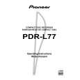
39k� TE 39k� MPP 10 : 1 VC 0.001µF 10:1 probe CH2 0.001µF 10 : 1 CH1 Oscilloscope
CN102 - pin 4 (TE) and pin 3 (MPP) RECORD button and REC MUTE button
Test Disc
STD-903
Adjust until the value of the output signals from pin 4 (TE) and pin 3 (MPP) of CN102 are the same, or the differential output of these signals is minimal. Sound broken, record characteristics deteriorate
Note: Adjustment must be done around mid-radius on a disc.
6.5.3 Tracking Offset Adjustment
Test Point Adjustment Point Adjustment Value
CN102 - pin 4 (TE) RECORD button and REC MUTE button 0 mV ± 10 mV
[Procedure]
(1) Press the AUTO/MANUAL button so that "03 F6" appears on the FL display. (2) Adjust with the RECORD button and the REC MUTE button until the above adjustment value to be reached is obtained. (3) Press the SET button to register the adjustment. Once the adjustment is registered with the SET button, "D.VOL" on the FL display lights.
TE 10 : 1 VC 10:1 probe Oscilloscope
Note: Perform the adjustment in Stop mode. This adjustment is possible with the low-pass filter used in adjustment 5 above attached.
55
|
|
|
> |
|