|
|
|
Who's Online
There currently are 6002 guests and
6 members online. |
|
Categories
|
|
Information
|
|
Featured Product
|
|
|
 |
|
|
There are currently no product reviews.
 ;
Thank you for your shop manual! Your help was very useful - the device is repaired! Once again - Thank you! I wish you a successful business! Edward (Russia).
;
It was a great experience,instead of purchasing a new Stereo Amplifier ,in just minutes i repaired my old one and that was thaks to the manual I have purchased from you.
Thanks again.
Samuel Alter
;
Das ging ja sehr unkompliziert hat bestens geklappt und die Quallität ist auch noch gut.
Vielen Dank dafür.
;
Everything okay, thanks a lot. It was a pleasure for me to make a deal with you.
;
A deal without problems, very fast and the manual is a good quality. Sorry for the my english.
PDR-555RW, PDR-V500, PDR-19RW, PDR-509
control. The spindle motor is controlled by switching the above three spindle servos (CAV, EFM-CLV and Wobble-CLV) and Stop mode by controlling the switch of the servo amplifier IC (PA9004A, IC247) according to the control signal output from the mechanismcontrol microcomputer.
7.6 AUDIO CIRCUITS
7.6.1 Analog Audio Input
The audio signal input via JA801 runs through the volume of the VR Assy once and returns to the AUDIO Assy. The input buffer circuit of IC803 (L-channel) and IC804 (R-channel) is a single-ended/differential conversion circuit composed invertinginverting circuits. The audio signal is converted to a differential signal and input to the IC801 A/D converter (AK5340-VS).
7.2 DEFECT CIRCUIT
The defect signal is output if there is a defect, such as a flaw, on the disc. If the defect signal is "Hi," the tracking error is muted and the low-frequency component of the error signal output just before the defect occurs is applied to the focus error and the spindle error so that the pliability rises.
7.6.2 A/D Converter
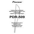
AK5340-VS, made by Asahi Chemical is used as the A/D converter. This is an 18-bit, 2-channel A/D converter, which employs fifthgeneration delta-sigma techniques. It contains two delta-sigma modulators and performs s 64-times oversampling of both channels simultaneously. The input range of the A/D converter is 4.0 Vp-p. So it becomes 0 dB when a signal of 2.08 Vp-p is input to input terminals AIN+ and AIN-. The control signals of the A/D converter are ADSTBY (pin 10), ADLRCK (pin 14), ADBCLK (pin 15), and ADDATA (pin 16). ADSTBY (pin 10) switches to Power-Down mode at "Hi" and offset calibration begins upon falling from "Hi" to "Lo." During the offset calibration, the input of each channel is measured as the data for it. At this moment, each audio input terminal is separated from the outside and short-circuited inside. ADLRCK (pin 14) is the signal from the encoder IC (IC308 LC89585, pin 36), and ADBCLK (pin 15) and ADDATA (pin 16) are signals for the encoder IC (pins 35 and 33).
7.3 EFM-DIGITAL PLL
Channel clocks are required to demodulate the EFM signal reproduced from the optical system, because it is modulated to 3T to 11T (where T is a cycle of the channel clock), which is integer multiple of T. Practically, the PLL must read the channel clock because the irregularities in the spindle rotation may change the pulse width of the EFM signal. This product has three stages of PLL. The first stage is a widerange PLL. The output of the first-stage PLL functions as the standard for all clocks in CXD2585Q. The PLL of the second stage is for generating high-frequency clock indispensable for the digital PLL of the third stage. The PLL of the third stage is a digital PLL for generating the practical channel clock.
7.4 RF DETECTION
For CD-Rs there is an RF detection circuit to distinguish recorded and unrecorded parts. The detection signal is output from the servo amplifier IC (PA9004A, IC247-pin 61). RFB and RFT also output the peak value and the bottom value of the HF signal used for OPC operation.
ADBCLK ADLRCK ADDATA MSB L ch LSB MSB R ch LSB
7.5 MIRROR CIRCUIT
A mirror signal equivalent to that of conventional CD players is used for CDs with EFM signals and for recorded parts of CD-Rs and CD-RWs. For unrecorded parts of a CD-R or CD-RW, the mirror signal peculiar to the CD decoder is generated using the RC (radial contrast) generated by crossing a groove.
Fig. 7-3 AK5340-VS data output timing
However, A/D Converter of PDR-509 uses PCM1800-1 made by the BURR-BROWN company.
30
|
|
|
> |
|