|
|
|
Who's Online
There currently are 5901 guests online. |
|
Categories
|
|
Information
|
|
Featured Product
|
|
|
 |
|
|
There are currently no product reviews.
 ;
Found this to be the manual included with the original packinging, was helpfull but did not give any detailed repair instructions.
 ;
Complete service manual, was very helpful in repairing this tapedeck.Thanks.
;
The service manual was a copy of the original from Wirlpool. The quality was good, all neccecary information was available including the service-codenumbers, so I could order the right part to be replaced for repair.
Downloding was no probem after the payment.
Thanks for the service!
;
Good,readable manual. I found other manuals that were not readable when it came to part ID, but the one downloaded from owner-manual.com was better than expected. I will do buisness with owner-manual.com again.
;
Service Manual that I received was very helpful to me. Thank you.
5
6
7
8
5.2.2 POWER SUPPLY UNIT
Flowchart of Failure Analysis for The POWER SUPPLY Unit
A
Failure analysis for the POWER SUPPLY Unit => PS1
STB 3.3 V power is not output.
Is the cable connected firmly to the P4 connector? Yes Is the cable to the P4 connector broken? No Is the cable connected firmly to the P9 connector? Yes Is the cable to the P9 connector broken? No Is the fuse (F001) blown? No Is one of the limiting resistors (R001/FR001) blown? No
No
Properly connect the cable between the P4 and D23 connectors.
Yes
Replace the defective cable (J104). POWER SUPPLY Unit.
Check the voltage at the DIGITAL Assy and
No
Properly connect the cable between the P9 and M2 connectors.
B
Yes Replace the defective cable (J106).
Yes Replace the POWER SUPPLY Unit.
Yes Replace the POWER SUPPLY Unit.
Check the resistance between F001 lead and the D002 anode, using a tester.
C
The POWER SUPPLY Unit is normal.
Failure analysis for the POWER SUPPLY Unit => PS2
The power is not on, even though the RELAY port is active.
No Is the relay (RL002) on? Yes No Is the PFC voltage normal? Yes The POWER SUPPLY Unit is normal.
Replace the POWER SUPPLY Unit.
� Check the relay operation at the terminal (Pin 11 of P4). (Voltage: 3.3 V) � Check the relay sound (click).
Replace the POWER SUPPLY Unit.
� Check the voltage between F301 lead (PFC OUT) and heat sink (primary GND) nearest F301. � The voltage must be around 390 V. Caution: High voltage!
D
Failure analysis for the POWER SUPPLY Unit => PS3
The cells of the panel do not light normally.
Is the VADR voltage within the specified values? Yes Is there a fluctuation in the VADR voltage? No Is the VSUS voltage within the specified range? Yes Is there a fluctuation in the VSUS voltage? No The POWER SUPPLY Unit is normal.
No
Replace the POWER SUPPLY Unit.
The specified voltage values are between 57 and 63 V.
E
Yes
Replace the POWER SUPPLY Unit.
The ripple must be within 5 V.
No
Replace the POWER SUPPLY Unit.
The specified voltage values are between 205 and 215 V (VSU: 125/35°C).
Yes Replace the POWER SUPPLY Unit.
The ripple must be within 10 V.
F
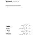
PDP-LX6080D
5 6 7 8
47
|
|
|
> |
|