|
|
|
Who's Online
There currently are 5989 guests online. |
|
Categories
|
|
Information
|
|
Featured Product
|
|
|
 |
|
|
There are currently no product reviews.
 ;
Was very fast and accurate service. Just what I needed. I recommend to everyone.
 ;
Very good scan quality, only PC Board scan not enough contrast.
;
First of all I must say that I received the manual in just a few minutes after placing the order. The copy is well done and very readable. I will buy others soon... Thanks, Meyer
;
Good service manual. I gat all I want. Copy is good, but could be better. All clear and useful. I sincerely recommend.
;
The schematic is very helpful and the images are very good.The schematic is very helpful and the images are very good.The schematic is very helpful and the images are very good.The schematic is very helpful and the images are very good.The schematic is very helpful and the images are very good.The schematic is very helpful and the images are very good.
1
2
3
4
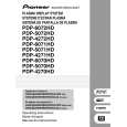
DELAY ADJUSTMENT OF THE CONTROL SIGNAL (SUS-B)
A
1 Measure the delay time for the SUS-U signal. 2 Check the delay time for the SUS-B signal. Adjust the variable control so that the SUS-B delay time becomes "SUS-U delay time + α ± 5 nsec." Note: For details on measuring points of waveform, see the figure below.
1.5 V SUS-U signal (input to the DRIVE Assy) 5V SUS-U signal (input to the DK module)
B
SUS-U delay time � Tsus-u 1.5 V SUS-B signal (input to the DRIVE Assy) 5V SUS-B signal (input to the MSK module) SUS-B delay time � Tsus-b
C
Value of α
SUS-B delay time: � Tsus-b Adjust so that "� Tsus-b = � Tsus-u + α ± 5 nsec," using the variable controls shown in the table below:
Assy X DRIVE Y DRIVE
VR VR1002 VR2010
Time 70 nsec 85 nsec
DELAY ADJUSTMENT OF THE CONTROL SIGNAL (SUS-G)
1 Measure the delay time for the SUS-D signal. 2 Check the delay time for the SUS-G signal. Adjust the variable control so that the SUS-G delay time becomes "SUS-D delay time + β ± 5 nsec." Note: For details on measuring points of waveform, see the figure below.
1.5 V SUS-D signal (input to the DRIVE Assy) 5V SUS-D signal (input to the DK module) SUS-D delay time � Tsus-d SUS-G signal (input to the DRIVE Assy)
E
D
1.5 V
5V SUS-G signal (input to the MSK module) SUS-G delay time � Tsus-g Value of β
SUS-G delay time: � Tsus-g
F
Assy X DRIVE Y DRIVE
VR VR1001 VR2011
Time 120 nsec 100 nsec
Adjust so that "� Tsus-g = � Tsus-d + β ± 5 nsec," using the variable controls shown in the table below:
132
1 2
PDP-6071PU
3 4
|
|
|
> |
|