|
|
|
Who's Online
There currently are 5856 guests online. |
|
Categories
|
|
Information
|
|
Featured Product
|
|
|
 |
|
|
There are currently no product reviews.
 ;
I was at first dubious about payiong for downloaded manuals but having done so, I was extremely impressed with quality of the two manual I ordered, well worth the small price I paid.
I would highly recommend these to my friends.
;
reasonable price for the schematic - the service is perfect, all as expected and pointed by instructions - good scan of the original plans - thank you!
;
Manual was just as described!!! I odered it and in less than a day was able to download it and the text was clear and pages were all complete just as the original manual was. Purcashed this for a friend and they were more than happy. Perfect all around!
 ;
Excellent service and prompt delivery. But it's not a manual - only 4 pages wiring diagrams.
Thanks.
;
The manual I purchased was exactly what I needed to repair my Toshica television. The manual contained schematics and troubleshooting information that was very helpful.
1
2
3
4
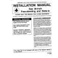
5.1.5 FLOWCHART OF FAILURE ANALYSIS FOR THE MAIN ASSY
A
Flowchart of Failure Analysis for The MAIN Assy
Failure analysis for the MAIN Assy. � MA1
The STB LED does not light although STB 3.3 V power is supplied. No
Failure in the RST IC (IC4801) output or its peripheral circuits
Is resetting of the IF microcomputer canceled? Yes
Replace the MAIN Assy.
B
Is the voltage at Pin 1 of the M5 connector low? Yes Is the M5 connector securely connected? Yes Is the cable that is connected to the M5 connector broken? No No problem with the MAIN Assy. Check the LED Assy.
No
Replace the MAIN Assy.
Failure in the line between the IF microcomputer and M5 connector
No
Securely connect the M5 connector.
Yes
Replace the cable (J113).
C
Failure analysis for the MAIN Assy. � MA2
The RELAY port does not work. The power is not turned on.
D
Is voltage at REQ_IF (3.3 V) on the MAIN Assy high? Yes
No
Can the unit be turned on, using the remote control unit? Yes
No
Replace the cable that connects the LED IR and MAIN Assys.
NG Replace the LED IR Assy.
Can the unit be turned on, using the Power switch on the side key? Yes Can the unit be turned on, using RS-232C commands?
No
Replace the cable that connects the SIDE KEY and MAIN Assys.
NG Replace the SIDE KEY Assy.
NG
Replace the MAIN Assy.
Failure in the RS-232C driver and its peripheral circuits
E
Is the power (1.8 V, 3.3 V) supplied to the main microcomputer? Yes Replace the MAIN Assy.
No
Replace the MAIN Assy.
If the voltage at Pin 129 (RST3 port) on the main microcomputer is high, it is judged that the AC power cord is not plugged in, and operation of the unit will stop there.
F
90
1 2
PDP-5071PU
3 4
|
|
|
> |
|