|
|
|
Who's Online
There currently are 6021 guests online. |
|
Categories
|
|
Information
|
|
Featured Product
|
|
|
 |
|
|
There are currently no product reviews.
 ;
This is a great site. I placed my order and by the next am it was available for download. Had some problems with some missing copy on some pages. Once I brought the error to the OMC's attention, the issue was resolved. I'll come back again.
 ;
Mi spiace per non poter scrivere in inglese... ma sono veramente soddisfatto del servizio offerto. Grazie..!!
;
The quality of this manual is good. It has all schematics and setup information for both the MDS-B3 and the MDS-B4. The scan quality is quite good, all pages are readable, This service manual also contains scans of the operating instructions from the User manual.
;
Quick site processing. A complete and very useful manual with all details. Thank you!
;
Das Service Manual war von der ersten bis zur letzten Seite sehr informativ und hilfreich. Die Darstellung aller Teile war klar und der Text gut lesbar.
Vielen Dank, das war nicht der letzte Download bei ownner-manuals.com.
5
6
7
8
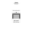
Charged Section
The places where the commercial AC power is used without passing through the power supply transformer. If the places are touched, there is a risk of electric shock. In addition, the measuring equipment can be damaged if it is connected to the GND of the charged section and the GND of the non-charged section while connecting the set directly to the commercial AC power supply. Therefore, be sure to connect the set via an insulated transformer and supply the current.
High Voltage Generating Point
The places where voltage is 100 V or more besides the live parts are described above. You must not touch them, since there is risk of electric shock. The VSUS voltage remains for several minutes after the power to the unit is turned off. These places must not be touched until about 10 minutes after the power is turned off, or it is confirmed with a tester that there is no residual VSUS voltage. 1. POWER SUPPLY Unit.....................................................(223V) 2. 50 X DRIVE Assy ...........................................(�230V to 223V) 3. 50 Y DRIVE Assy ...........................................................(353V) 4. 50 SCAN A Assy ............................................................ (353V) 5. 50 SCAN B Assy ............................................................ (353V) 6. X CONNECTOR A Assy ................................(�230V to 223V) 7. X CONNECTOR B Assy ............................... (�230V to 223V) Discharge the VSUS voltage, as shown below: [Method for discharging the VSUS voltage] 1. Set DRF_SW on the DIGITAL VIDEO Assy to ON (Drive OFF status). �1, �2 2. Leave the switch at that position for about 20-30 seconds. 3. If the power is on, turn it off. Then return DRF_SW to the OFF position. �3 Notes �1: You can also set the unit to "Drive OFF status" by sending the "DRF" RS232C command from the PC. �2: DRF_SW can be switched whether the power is on or off. �3: Power-down will occur if DRF_SW is set to OFF while the power is on. (See "7.1.5 POWER ON/OFF FUNCTION FOR THE LARGE-SIGNAL SYSTEM".)
POWER SUPPLY Unit 50 X DRIVE Assy X CONNECTOR B Assy
A
1. Power Cord 2. AC Inlet with Filter 3. Power Switch (S1) 4. Fuse (In the POWER SUPPLY Unit) 5. STB Transformer and Converter Transformer (In the POWER SUPPLY Unit) 6. Other primary side of the POWER SUPPLY Unit
B
C
50 inch model
: Part is Charged Section. : Part is the High Voltage Generating Points other than the Charged Section. 50 SCAN B Assy 50 Y DRIVE Assy
D
E
50 SCAN A Assy
Power Switch (S1)
AC Inlet with Filter
X CONNECTOR A Assy Power Cord
F
Fig.1 Charged Section and High Voltage Generating Point (Rear view)
PDP-504CMX/1
5 6 7 8
5
|
|
|
> |
|