|
|
|
Who's Online
There currently are 5631 guests online. |
|
Categories
|
|
Information
|
|
Featured Product
|
|
|
 |
|
|
There are currently no product reviews.
 ;
Incredibly clear!!!! Well done, complete and wonderful. It could not better than this!!!!
 ;
Thank You for fast delivery for the sheme.
Everything allright.
Thanks & best regards Franz
;
again you did a very good job. It was fast too. Photocopy are really readable and clear
;
Probably it never existed a 1081 official service manual from Commodore, it's look more like a NAPCEC service manual & diagrams compilation of the 1084 series and his variants, like the nap6523, 8cm505, 1084S, 1084P and obviously the 1081. It's more complete than other scans and the quality of the scans also are far superior. It has two circuit diagrams variants of the 1081, mono and stereo versions. It doesn't include a diagram for the Philips CM8500 or CM8501, they look like the 1081 but they are slightly different.
;
Rapid, clear well done as all the scheme I downloaded from this site. Great job very functional and very useful
1
2
3
4
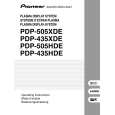
Charged Section
A
High Voltage Generating Point
The places where voltage is 100V or more except for the charged places described above. If the places are touched, there is a risk of electric shock. 1. POWER SUPPLY Unit................................................... (223V) 2. 50 X DRIVE Assy .......................................... (�230V to 223V) 3. 50 Y DRIVE Assy .......................................................... (353V) 4. 50 SCAN A Assy ............................................................ (353V) 5. 50 SCAN B Assy ............................................................ (353V) 6. X CONNECTOR AAssy ................................ (�230V to 223V) 7. X CONNECTOR B Assy ............................... (�230V to 223V)
The places where the commercial AC power is used without passing through the power supply transformer. If the places are touched, there is a risk of electric shock. In addition, the measuring equipment can be damaged if it is connected to the GND of the charged section and the GND of the non-charged section while connecting the set directly to the commercial AC power supply. Therefore, be sure to connect the set via an insulated transformer and supply the current.
B
1. AC Power Cord 2. AC Inlet with Filter 3. Power Switch (S1) 4. Fuse (In the POWER SUPPLY Unit) 5. STB Transformer and Converter Transformer (In the POWER SUPPLY Unit) 6. Other primary side of the POWER SUPPLY Unit
Discharge the VSUS voltage, as shown below: [Method for discharging the VSUS voltage] 1. Set DRF_SW on the DIGITAL VIDEO Assy to ON (Drive OFF status). *1, 2 2. Leave the switch at that position for about 20-30 seconds. 3. If the power is on, turn it off. Then return DRF_SW to the OFF position. *3 Notes *1: You can also set the unit to "Drive OFF status" by sending the "DRF" RS232C command from the PC. *2: DRF_SW can be switched whether the power is on or off. *3: Power-down will occur if DRF_SW is set to OFF while the power is on. (See "7.1.6 Power on/off function for the largesignal system".)
C
: Part is Charged Section. : Part is the High Voltage Generating Points other than the Charged Section. 50 SCAN B Assy 50 Y DRIVE Assy POWER SUPPLY Unit 50 X DRIVE Assy
D
X CONNECTOR A Assy
E
X CONNECTOR B Assy
50 SCAN A Assy
AC Inlet with Filter
Power Cord
Power Switch (S1)
F
Fig.1 Charged Section and High Voltage Generating Point (Rear View)
4
1 2
PDP-505PE
3 4
|
|
|
> |
|