|
|
|
Who's Online
There currently are 6043 guests online. |
|
Categories
|
|
Information
|
|
Featured Product
|
|
|
 |
|
|
There are currently no product reviews.
 ;
This service manual includes drawings, schematics, exploded views, parts list, operating details, and more. Very good scans, very readable. The only thing that made it a 4 star rating was on approximately 4 scans only half of the page was scanned then the other half. I would have preferred the pages to be whole scans.
 ;
Good manual contains all it takes to update, repair,these types of mixers.Thanks.
;
Great service. Fast response. High quality scan. Good price.
Thank you very much!!!
Oleg S.
;
Well-scanned, complete manual. Contains the information needed for repair and maintenance.
;
It's great to be able to obtain a precious technical information for a real old equipment. The one I got helps me a lot in the area of wiring diagram to repair my antique. PDF gave me clear enough information to find out thr details. Thanks for giving me the oppotunity to be able to access to almost vanished informations.
5
6
7
8
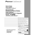
Charged Section
The places where the commercial AC power is used without passing through the power supply transformer. If the places are touched, there is a risk of electric shock. In addition, the measuring equipment can be damaged if it is connected to the GND of the charged section and the GND of the non-charged section while connecting the set directly to the commercial AC power supply. Therefore, be sure to connect the set via an insulated transformer and supply the current.
High Voltage Generating Point
The places where voltage is 100 V or more besides the live parts are described above. You must not touch them, since there is risk of electric shock. The VSUS voltage remains for several minutes after the power to the unit is turned off. These places must not be touched until about 10 minutes after the power is turned off, or it is confirmed with a tester that there is no residual VSUS voltage. 1. POWER SUPPLY Unit.....................................................(223V) 2. 50 X DRIVE Assy ...........................................(�230V to 223V) 3. 50 Y DRIVE Assy ...........................................................(353V) 4. 50 SCAN A Assy ............................................................ (353V) 5. 50 SCAN B Assy ............................................................ (353V) 6. X CONNECTOR A Assy ................................(�230V to 223V) 7. X CONNECTOR B Assy ............................... (�230V to 223V) Discharge the VSUS voltage, as shown below: [Method for discharging the VSUS voltage] 1. Set DRF_SW on the DIGITAL VIDEO Assy to ON (Drive OFF status). �1, �2 2. Leave the switch at that position for about 20-30 seconds. 3. If the power is on, turn it off. Then return DRF_SW to the OFF position. �3 Notes �1: You can also set the unit to "Drive OFF status" by sending the "DRF" RS232C command from the PC. �2: DRF_SW can be switched whether the power is on or off. �3: Power-down will occur if DRF_SW is set to OFF while the power is on. (See "7.1.5 POWER ON/OFF FUNCTION FOR THE LARGE-SIGNAL SYSTEM".)
POWER SUPPLY Unit 50 X DRIVE Assy X CONNECTOR B Assy
A
1. Power Cord 2. AC Inlet with Filter 3. Power Switch (S1) 4. Fuse (In the POWER SUPPLY Unit) 5. STB Transformer and Converter Transformer (In the POWER SUPPLY Unit) 6. Other primary side of the POWER SUPPLY Unit
B
C
50 inch model
: Part is Charged Section. : Part is the High Voltage Generating Points other than the Charged Section. 50 SCAN B Assy 50 Y DRIVE Assy
D
E
50 SCAN A Assy
Power Switch (S1)
AC Inlet with Filter
X CONNECTOR A Assy Power Cord
F
Fig.1 Charged Section and High Voltage Generating Point (Rear view)
PDP-504CMX/1
5 6 7 8
5
|
|
|
> |
|