|
|
|
Who's Online
There currently are 5941 guests online. |
|
Categories
|
|
Information
|
|
Featured Product
|
|
|
 |
|
|
There are currently no product reviews.
 ;
I have this hi-fi system for a long time and I need to repair some things. Founding this manual will be very helpfull :)
 ;
It is pretty good. The schematics were covered all components, the manual also provide the parts list . It's useful for the trouble shooting.
;
Very fast service, best quality of the service manual and the schematics
;
This service manual of the old video cassette recorder VT-LC50EM is very good readable even the tiniest numbers (i.e. IC-pins). The circuits are very clear. Many details of the schematic are very good described but in GERMAN language. Many schematic details - but complete at all. Common background information of several details are enclosed and physical knowledge of the TFT liquid crystal display for example. The manual lacks PCB drawings. If you understand german I would recommend this manual for you.
;
Hi, this is a very clear manual, nice copy, not quite up to the standard of the very best available but better than many others. I think the price was especially fair for a hard to find manual and I would certainly use this manual seller again. Recommended.
1
2
3
4
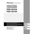
5.1.5 FLOWCHART OF FAILURE ANALYSIS FOR THE MAIN ASSY
A
Flowchart of Failure Analysis for The MAIN Assy
Failure analysis for the MAIN Assy. � MA1
The STB LED does not light although STB 3.3 V power is supplied.
Is the M1 connector securely connected? Yes
No
Securely connect the M1 connector.
B
Is the cable that is connected to the M1 connector broken? No Is resetting of the IF microcomputer canceled? Yes Is the voltage at Pin 1 of the M5 connector high? Yes Is the M5 connector securely connected?
Yes
Replace the cable (J207).
No
Replace the MAIN Assy.
Failure in the RST IC (IC4801) output or its peripheral circuits
No
Replace the MAIN Assy.
Failure in the line between the IF microcomputer and M7 connector
No
Securely connect the M5 connector.
C
Yes Is the cable that is connected to the M5 connector broken? No No problem with the MAIN Assy. Check the LED Assy. Yes Replace the cable (J113).
Failure analysis for the MAIN Assy. � MA2
D
The RELAY port does not work. The power is not turned on.
Is voltage at REQ_IF (3.3 V) on the MAIN Assy high? Yes
No
Can the unit be turned on, using the remote control unit? Yes
No
Can the unit be turned on, using No the Power switch on the main unit? Yes
Replace the cable that connects the SIDE KEY and MAIN Assys. NG Replace the MAIN Assy. NG
Replace the cable that connects the LED IR and MAIN Assys.
NG Replace the cable that connects the LED IR and MAIN Assys. NG
E
Can the unit be turned on, using No the Power switch on the main unit? Yes Replace the cable that connects the SIDE KEY and MAIN Assys.
Replace the LED IR Assy.
NG Replace the cable that connects the SIDE KEY and MAIN Assys. NG Replace the SIDE KEY Assy.
Replace the MAIN Assy. Is the power (1.8 V, 3.3 V) supplied to the main microcomputer? No Replace the MAIN Assy.
� Failure in the REC IC (IC4402) and PM SW (IC4407) outputs � Does the voltage remain low even though it should be active? � A shutdown, indicated by 9 flashes of LED, will be established in 20 seconds.
F
Yes Replace the MAIN Assy.
If the voltage at Pin 129 (RST2 port) on the main microcomputer is high, it is judged that the AC power cord is not plugged in, and operation of the unit will stop there.
82
1 2
PDP-427XD
3 4
|
|
|
> |
|