|
|
|
Who's Online
There currently are 6040 guests and
3 members online. |
|
Categories
|
|
Information
|
|
Featured Product
|
|
|
 |
|
|
There are currently no product reviews.
 ;
Great tape deck manual!
I'm very positively surprised, because it is a very long manual, lot of pages, drawings, diagrams, description of how to make the alignment and adjustment procedures.
It is as good as the old "Naka" manuals from the 1970's - if somebody have seen them, they know what I mean by that.
I recommend to buy this very much !
;
I am a vintage hifi collector. No way to fix that device without the appropriate service manual...thanks to your site I got it and every thing is easier now. I got the manual right after ordering: fast cheap accurate ... thank you
;
Wonderful job clear. Qick fantastic. These people are really good. If even a problem arise they are wonderful assisting you. These scheme is so net despite this is a very old TV. Thank you for everything!!!!!!!!
;
Detailed schematic diagram, manual for professionals
;
Good service manual,exploded view,adjusment and test point locations,head alignment,mechanical checks and adjusments,all perfect.
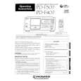
PD-F407
1. SAFETY INFORMATION
This service manual is intended for qualified service technicians; it is not meant for the casual do-it-yourselfer. Qualified technicians have the necessary test equipment and tools, and have been trained to properly and safely repair complex products such as those covered by this manual. Improperly performed repairs can adversely affect the safety and reliability of the product and may void the warranty. If you are not qualified to perform the repair of this product properly and safely, you should not risk trying to do so and refer the repair to a qualified service technician.
IMPORTANT THIS PIONNER APPARATUS CONTAINS LASER OF CLASS 1. SERVICING OPERATION OF THE APPARATUS SHOULD BE DONE BY A SPECIALLY INSTRUCTED PERSON.
LASER DIODE CHARACTERISTICS MAXIMUM OUTPUT POWER : 5 mw WAVELENGTH : 780-785 nm
LABEL CHECK For (PD-F407/WPWXJ only)
Additional Laser Caution
1. Laser Interlock Mechanism The position of the switch (S651) for detecting loading state is detected by the system microprocessor, and the design prevents laser diode oscillation when the switch (S651) is not on CLMP terminal side (CLMP signal is OFF or high level). Thus, the interlock will no longer function if the switch (S651) is deliberatery set to CLMP terminal side. (low level) The interlock also does not function in the test mode V. Laser diode oscillation will continue, if pin 33 of CXA1782CQ (IC151) on the MOTHER BOARD ASSY is connected to GND, or pin 26 of IC351 (LDON) is connected to low level (ON), or else the terminals of Q151 are shorted to each other (fault condition).
AR RE
2. When the cover is opened, close viewing of the objective lens with the naked eye will cause exposure to a Class 1 laser beam. V : Refer to page 25. on the service manual RRV1877.
2
|
|
|
> |
|