|
|
|
Who's Online
There currently are 6043 guests online. |
|
Categories
|
|
Information
|
|
Featured Product
|
|
|
 |
|
|
There are currently no product reviews.
 ;
Impressively thorough. Even the simple operators manual helped me "fix" one of the 2 CD players in the unit. This unit reads CD's from the top so they should be installed in the magazines "upside down" from typical CD players. The CD player service manual helped me unjam a stuck carriage because somebody transported the box laying down loaded with CD's. A little lens cleaning & the player now works well! Thanks for you help at a great price! Joe
;
I was skeptical at first but later found the manual to be good quality for the price. It took a couple hours to receive the email with the download link, well worth the wait. Thanks.
;
very helpful, I could not have cleaned motherboard and replaced the main fan without it
 ;
Good manual, schematics nice and clear with good quality scanning. Woul dhave been nice to have immediate access after purchasing though.
;
I was very glad recieving the service manal from You. Manuals were delivered promptly and were correct as advertised. A complete and very usefull service manual with all details. Thank you!
M-AX10
Descriptions of the Block Diagram
1. INPUT switching block Four small-signal relays for individual channels are used for input signal switching. 2. 12-dB flat amplifier block The input signal is amplified by 12 dB (4 times) to increase the input level at the DAC attenuator block to improve the dynamic range and signal-to-noise ratio. In DUAL or BRIDGE mode, the flat amplifier on the low-channel side is shut down by the LOCAL CIRCUIT OFF circuit. The circuits are mounted in a shielded box to completely eliminate electrostatic and magnetic coupling. 3. DAC attenuator block Attenuator section This is a digitally controlled high-precision analog attenuator that uses a ladder resistance block of R-2R-type DAC ICs for volume control. The signal is input to the Vref (reference-voltage) terminal and the attenuated signal current is obtained from the Iout (currentoutput) terminal. The signal at this terminal is converted to a voltage signal by an I-V converter of the operational amplifier. An output signal of the same phase as the input signal is obtained through inversion by the operational amplifier. The attenuation volume adjustment is controlled using serial data from the microcomputer. Control section A 5-bit (31-position) digital rotary switch is used. The rotation angle and information can be sent to the microcomputer, enabling the silent function (Low-Power-Consumption mode) of the microcomputer.
Input 1, 2
5. Protection circuit When a DC voltage at the output end or a short circuit at the load end is detected, hardware muting is activated and muting and output relays are controlled by the microcomputer. When a short circuit at the load end is detected, a resistance inserted between the MOSFET drain power sources is used (for current detection) in place of a bridge detection circuit, a device greatly affected by the phase difference between the output power voltage and current. Thus, possible malfunction of the protection circuit in practical use is prevented. 6. Power block A large (450-VA) Super Ring is employed for the transformer. The second coils are separated into three coil windings for left channel, right channel, and a subcircuit. For the power amplifier, a full-wave voltage doubler rectifier system is used to suppress high-frequency current. For the voltage amplifier, a half-wave voltage doubler rectifier system is used to obtain the specified voltage without using additional coils. Each signal stage has a local stabilized power source, and the lamps are driven at a constant current for low power consumption.
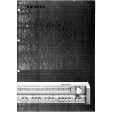
Level Diagram
12dB Input high, low Input Buffer Amp. ATT ON 14dB Dual, Separate 20dB Bridge ATT through Speaker Out Power Amp.
Two DAC ICs are used for two individual channels. There is no mechanical contact, resulting in fewer errors in attenuation volume and gang errors within 0.1 dB at any position. The attenuation volume can be flexibly adjusted by the microcomputer software. With this product, it can be set in 2-dB steps (up to -58 dB) in BRIDGE mode and in 0.5 dB steps (up to -15 dB) in SEPARATE mode. When this product is used in combination with a preamplifier, you can bypass the DAC attenuator block using the ATT.THROUGH function. For this bypass switching, the same small-signal relay as with the INPUT switching clock is used. 4. 14-dB power amplifier block Pioneer's original "Direct-Energy MOSFET Amplifier" and "WideRange Linear Circuits" are mounted. The circuits function as the inversion/noninversion switching amplifier on the high-channel side and as an inversion amplifier in BRIDGE mode. This eliminates the necessity for an inversion amplifier otherwise essential for a bridge amplifier.
0dB (-58dB MIN) DAC VR
40dBV (100Vrms) 30dBV
40Vrms, 32dBV Bridge 20Vrms, 26dBV
20dBV (10Vrms) 10dBV 0dBV (1Vrms) -10dBV
Maximum permission input level with attenuator (4Vrms) 4Vrms, 12dBV
Dual Separate
1Vrms
57
|
|
|
> |
|