|
|
|
Who's Online
There currently are 5619 guests and
1 member online. |
|
Categories
|
|
Information
|
|
Featured Product
|
|
|
 |
|
|
There are currently no product reviews.
 ;
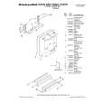
The AKAI 1720 model reel to reel tape recorder described in this Manual is quite an old unit - circa late 1960's. As a consequence, the description of the mechanical details - and adjustments thereof - is quite critical. The manual does this quite well. The schematics are also well presented and have detailed PCB overlays. Probably the only negative is that some half-tone detail has been lost from the original manual as it has been scanned in simple B&W.
 ;
Perfect source for service manuals: fast and professional transaction; high quality, perfect readable and largely scaleable PDF; complete schemes, diagrams and spare part list. Tnx a lot, cu again!!!!
;
I got your link from a friend and I must say that I am really satisfied with your service. Specially this B&O manual I didn't find anywhere on the web... but you could deliver it :-) . You deliver very fast and the copy is of good quality. So your webpage is bookmarked. Thanks
;
This was the Sony CCU-500A Service manual I was looking for.
The price was reasonable.
The permission to download was quck.
I will use Owner-Manual.com for all my manual needs.
;
Excellent printing quality.
A complete and very usefull service manual with all details.
GREAT SERVICE AT VERY LOW PRICE!
A+++++++++++++++++++++++++
GM-X822,X722
26
Three-channel mode, two-way system Connecting Speaker Band-pass filter (combination of Setting the Filter Constant
wires low-pass and high-pass filter
Low-pass filter (for subfor mid-bass/mid): 6 dB/octave
L2 C2
The speaker output mode can be two-channel (stereo), one-channel (mono), or threeC1 channel (stereo + mono). Connect the 6 dB/octave �6dB speaker leads suit the mode according to
woofer/woofer):
Mid-high (Left) 0dB
L1 Woofer (Mono) 0dB
L1
figures on the following pages.
� When connecting to the speaker input, do not �6dB fCL fCH 2fCH
f connect the speaker input. � A multi-channel system can be set up using a
connect the RCA output. C1 Mid-high (Right) 2 combination of filters. The inductance (L) and
� When connecting to the RCA input, do not
fC 2fC
Two-channel mode (stereo) Three-channel mode, three-way system capacitance (C) will determine the frequency (fc) High-pass filter (for mid/mid-high): that speaker will reproduce. Refer to the chart
High/mid-high
C1 (Left)
� Use the capacitors specified. Non-polarized
C1 0dB capacitors rated at over ±25 V should be used for
below to determine the components required. 6 dB/octave C1 and C2 in diagram. Because of the voltage Mid/mid-bass (Left)
output L2 C2 of the amplifier, it is very important to use Speaker non-polarized capacitors rated at or over 25 V. (Right) Woofer/sub-woofer This will prevent a safety hazard.
L1 fC f C
(Left) �6dB
f
(Mono) 2 (Right) High/mid-high
L2 C2 Mid/mid-bass
One-channel mode (mono) (Right)
� Inductors (L1 and L2 in the diagrams) act as low-pass filters. Capacitors (C1 and C2 in the diagrams) act as high-pass filters. Inductors (L) are used for the Speaker load Impedance 2 4 8 � woofer/sub-woofer, and capacitors (C) are used for the high/mid-high. 50 6.4 1,600 12.70 800.0 25.50 400.0 � Remember when bridging an amplifier it 80 4.0 1,000 8.00 500.0 16.00 250.0 will see only half of the original speaker 125 2.5 640 5.10 300.0 10.00 160.0 impedance. Therefore, you must use speakers that have ratings of 4 ohms or higher. If you use speakers that have 320 1.0 250 2.00 125.0 4.00 62.0 lower impedance ratings it may cause 500 0.64 160 1.30 80.0 2.60 40.0
200 1.6 400 3.20 200.0 6.40 100.0 800 0.4 100 0.80 50.0 1.60 25.0
Component Guide
Speaker (Mono) fc (Hz) L (mH) C (µF)
Three-channel mode (stereo + mono) damage to the amplifier.
solder them so they cannot be pulled combining the stereo and mono modes loose. Tape or use heat shrink on the using inductors and capacitors. 3,200 0.1 25 0.20 12.5 0.40 6.2 joints to prevent short circuits. 5,000 0.06 16 0.13 8.0 0.26 4.0
The power amplifier is basically a two� When the inductors and capacitors are channel/one-channel bridgeable amplifier, connected to the speaker wires, secure or 1,250 0.25 64 0.50 30.0 1.00 16.0 but three channels can be achieved by 2,000 0.16 40 0.30 20.0 0.64 10.0
8,000 0.04 10 0.08 5.0 0.16 2.5 10,000 0.03 8 0.06 4.0 0.13 2.0
|
|
|
> |
|