|
|
|
Who's Online
There currently are 5980 guests and
2 members online. |
|
Categories
|
|
Information
|
|
Featured Product
|
|
|
 |
|
|
There are currently no product reviews.
 ;
Very clear copy of the philips service manual. Fast delivery. Thank you very much
;
Excellent manual, detailed, very useful! Exactly what I needed, I'd recommend it to all who need it. Although images are scanned easily readable and explicit. A valuable tool product at a price more than modest, take it with confidence and you will not regret it!
;
Clear and complete service manual. Easy now to restore my old Kenwood KD-1500.
Thanks a lot.
;
Thanks for this "hard to find" service manual. This Sony PS212A is a very good turntable that needed to be restored !
 ;
Excellent quality on these manuals. Same as having the original printed manual and incredibly useful when doing a custom install like me. Keep it up on the good work.
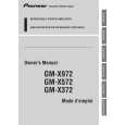
Connecting the Unit
Connecting the Power Terminal
� Always use the special red battery and ground wire [RD-223], which is sold separately. Connect the battery wire directly to the car battery positive terminal (+) and the ground wire to the car body.
Installation
4. Connect the wires to the terminal.
� Fix the wires securely with the terminal screws. GND terminal System remote control terminal System remote control wire Ground wire Speaker output terminal Battery wire Speaker wire Power terminal
3. Connect the speaker wires to the speaker output terminals.
� Connect the speaker wires, passing them through the terminal cover. � Fix the speaker wires securely with the terminal screws. Terminal screw
Using the Speaker Input
Connect the car stereo speaker output wires to the amplifier using the supplied speaker input connector.
� Do not connect both the RCA input and the speaker input at the same time.
Connecting the Speaker wires
The speaker output mode can be two-channel (stereo) or one-channel (mono). Connect the speaker leads to suit the mode according to the figures shown below.
� Do not connect both the RCA input and the speaker input at the same time.
CAUTION
� Do not install in: �Places where it could injure the driver or passengers if the vehicle stops suddenly. �Places where it may interfere with the driver, such as on the floor in front of the driver�s seat. Make sure that wires are not caught in the sliding mechanism of the seats, resulting in a short-circuit. Confirm that no parts are behind the panel when drilling a hole for installation of the amplifier. Protect all cables and important equipment such as fuel lines, brake lines and electrical wiring from damage. Install tapping screws in such a way that the screw tip does not touch any wire. This is important to prevent wires from being cut by vibration of the car, which can result in fire. To prevent electric shock, do not install the amplifier in places where it might come in contact with liquids. To ensure proper installation, use the supplied parts in the manner specified. If any parts other than the supplied ones are used, they may damage internal parts of the amplifier, or they may become loose causing the amplifier to shut down.
Example of installation on the floor mat or on the chassis
1. Place the amplifier where it is to be installed. Insert the supplied tapping screws (4 � 18 mm) into the screw holes. Push on the screws with a screwdriver so they make marks where the installation holes are to be located. 2. Drill 2.5 mm diameter holes at the point marked, and install the amplifier, either on the carpet or directly to the chassis.
Tapping-screws (4 � 18 mm)
1. Pass the battery wire from the engine compartment to the interior of the vehicle.
� After making all other connections to the amplifier, connect the battery wire terminal of the amplifier to the positive (+) terminal of the battery. Engine Fuse (30 A) compartment Interior of the vehicle
Two-channel mode (stereo) 7 Connections when using the speaker input
Terminal cover Car Stereo
� �
� (Right) Speaker (Left)
Speaker output
� �
Fuse (30 A) Positive terminal Insert the O-ring rubber grommet into the vehicle body.
Drill a 14 mm hole into the vehicle body.
Connecting the Speaker Output
4. Push on the terminal cover.
Terminals
1. Expose the end of the speaker wires using nippers or a cutter by about 10 mm and twist.
Twist
One-channel mode (mono)
White/black: Left â� White: Left + Gray/black: Right â� Gray: Right +
To prevent malfunction
� To ensure proper heat dissipation of the amplifier, be sure of the following during installation. �Allow adequate space above the amplifier for proper ventilation. �Do not cover the amplifier with a floor mat or carpet. � Do not install the amplifier near a door where it may get wet. � Do not install the amplifier on unstable places such as the spare tire board. � The best location for installation differs with the car model and installation location. Secure the amplifier at a sufficiently rigid location. � Make temporary connections first and check that the amplifier and the system operate properly. � After installing the amplifier, confirm that the spare tire, jack and tools can be easily removed.
2. Twist the battery wire, ground wire and system remote control wire.
Twist
10 mm
2. Attach lugs to speaker wire ends. Lugs not supplied. 3. Attach lugs to wire ends. Lugs not supplied.
� Use pliers, etc., to crimp lugs to wires. Lug Speaker wire Ground wire Lug Battery wire � Use pliers, etc., to crimp lugs to wires. Lug Speaker input connector To speaker input terminal of this unit. Speaker (Mono)
Floor mat or chassis Drill a 2.5 mm diameter hole
|
|
|
> |
|