|
|
|
Who's Online
There currently are 6043 guests online. |
|
Categories
|
|
Information
|
|
Featured Product
|
|
|
 |
|
|
There are currently no product reviews.
 ;
Good manual contains all it takes to update, repair,these types of mixers.Thanks.
;
Great service. Fast response. High quality scan. Good price.
Thank you very much!!!
Oleg S.
;
Well-scanned, complete manual. Contains the information needed for repair and maintenance.
;
It's great to be able to obtain a precious technical information for a real old equipment. The one I got helps me a lot in the area of wiring diagram to repair my antique. PDF gave me clear enough information to find out thr details. Thanks for giving me the oppotunity to be able to access to almost vanished informations.
;
Another excellent aquisition. Fine detailed manual. Thanks
5
6
7
8
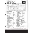
Removing the Amp Unit (Fig. 3)
Amp Unit
Heat Sink
A
1 Remove six black screws (M3 x 10). 2 Remove six white screws (M3 x 12). A Screw holes in the PCB are printed with
numbers 1 to 12. Remove screws in numerical order. Re-assembly takes the reverse order of disassembly. Caution) The Amp Unit is adhered on the Heat Sink with silicon grease. This means forcibly removing the Amp Unit from the Heat Sink may break the PCB.
1
1 3
1
2
2
2
B
2
2 3
2 1
1
1
3
Remove all of the twelve screws. Then, remove the two black screws (M3 x 5). Tighten screws whose length is M3 x 8 or more into the two screw holes so as to raise the Amp Unit above the Heat Sink. Then, remove the Amp Unit. (Since screw threads differ, 1 and 2 screws cannot be used.)
C
Fig. 3
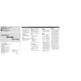
Caution when re-assembling the Amp Unit and the Heat Sink
Be aware that the RCA Terminal may break unless the Amp Unit and the Heat Sink are assem-bled following the correct procedures given below. 1) Secure the RCA-side Panel on the Heat Sink with screws. (Fig. 2) 2) Place the Amp Unit on the Heat Sink aligning with two studs. (Fig. 4) 3) Move the Amp Unit until the RCA Holder on the Amp Unit comes in contact with the inside of the Panel. (Fig. 4) Caution in steps 2) and 3) When you place the Amp Unit on the Heat Sink, you will find no positioning marks to determine the direction of two panels. To position them correctly, the Amp Unit needs to be moved to the place where it comes in contact with the RCA-side panel. If you do not position them, an excessive force can be applied to the RCA Terminal. This may result in breakage. 4) Secure the RCA-side Panel and the RCA Holder with screws. (Fig. 2) 5) Secure the Amp Unit on the Heat Sink with screws. (Fig. 3) 6) Secure the Panel for the Power Terminal side in place with screws. (Fig. 2)
RCA Holder
RCA Terminal (CN111)
Amp Unit
D
A
Move the Amp Unit
E
Heat Sink Panel for the RCA side Stud Stud
Fig. 4
F
GM-5100T/XU/EW
27 7 8
5
6
|
|
|
> |
|