|
|
|
Who's Online
There currently are 5883 guests and
2 members online. |
|
Categories
|
|
Information
|
|
Featured Product
|
|
|
 |
|
|
There are currently no product reviews.
 ;
nice completed SERVICE MANUAL as the description THANK YOU !!!-
;
Hard to find service manual describing the PLL circuit of the AKAI AP-306.
Thanks to have it available.
;
Gut, sehr gut! It helps me much! I couldn't find this schema nowhere. Good quality
DV-515
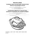
1.2.3 Tracking / Slider Servo
ATB: For phase differential TE (use for DVD), the tracking balance compensation is achieved by outputting the offset from the TBAL output at pin 44 of the digital servo IC, and by biasing the charge pump resistor for phase-difference error of RFIC. For 3-beam TE (use for CD), the tracking balance compensation is achieved by adjusting the gain balance of A and C in RFIC with the voltage of RFIC-pin 30. The difference is detected by processing TE at pin 32 of IC 201 with an internal digital equalizer. TDO: In addition to the servo output, the lowband components, such as the kick-brake for jump, are added for TDO output. SLDO: The low-band components of TE are processed by the internal digital equalizer, and deadband is added for SLDO output. The offset voltage for pickup movement is also included in the SLDO output.
C A
� TRACKING / SLIDER SERVO
PICKUP TE RF OEIC B1 B2 B3 B4
5 6 7 9 13 14 30 35
TE
32
IC101 RFIC LA9701M 8
TBAL
39
CP
IC501 ADDRESS MECH. IC201 DIGITAL & CONTROL BUS 44 SERVO IC PE5012A LC78651W
48
45
TRKG COIL
11 12
6
TDO SLDO
IC151 DRIVER 26 15
16
M SLDR
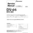
1.2.4 SPINDLE SERVO
For a CD, the RF signal output from pin 46 of the RF IC is converted to binary in IC201. By comparing the binary value with the reference CLK (clock), the SPDL ERR signal is output from pin 46. � SPDL SERVO
RF IC101 RFIC LA9701M
46
For a DVD, the SPDL ERR signal is generated from the PWM signal output from LSI-��. Upon receiving this signal via pin 29, IC201 also outputs it from pin 46, switching from the CD SPDL ERR signal.
ATC
179 200
OEIC
3
54
RFO CLK (27M)
IC301 3 A/D ADC1175CIJMX |
12
10
8 bit
| 207
RF
176
IC701 LSI II PD4833A
APC AFC IC302 (1/2)
39
178 180 177 161 163 166 168 95 159
ASC
VCO
FG
IC201 DIGITAL SERVO 29 55 LC78651W
46
FPWM VPWM IC261 (2/2) V165 IC261 (1/2) FG PPWM RPWM DUTY50
SPDL +12 SPDL M SPDL 13
IC251 DRV 25 BA6195FP (Base)
SPDO
5
|
|
|
> |
|