|
|
|
Who's Online
There currently are 6043 guests online. |
|
Categories
|
|
Information
|
|
Featured Product
|
|
|
 |
|
|
There are currently no product reviews.
 ;
Complete service and operation manual. All schematics are there, all circuit boards AND add-on boards. Including exploded views ,component names and specifications. Also electrical and mechanical adjustment procedures are in this manual. This manual also covers the more advanced BR-S811E unit. Scan quality is fair and usable.
 ;
High quality scan of original Service Manual. Everything´s fine!
;
Good scan of the original service manual. All schematics and adjustment procedures are there. It helped me to fix a long lasting problem with the tracking circuitry. The manual also includes the supplementals 1,2 and 3. Included are; electrical schematic's , pcb layout's, mechanical drawing's and exploded views, disassembly manual and maintenance procedures. 236 pages.
;
The Service Manual received was helpful. The electronic information is exactly what I needed.
I recomend all of my friends about this technical page.
;
High quality scan of service manual. I am satisfied!
5
6
7
8
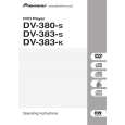
7.2 DISASSEMBLY
REMOVAL OF MECHANICAL PARTS AND P.C. BOARDS
1-3: DVD DECK (Refer to Fig. 1-3) 1. Short circuit the position shown in Fig. 1-3 using a soldering iron. If you remove the DVD Deck with no soldering, the Laser may be damaged. 2. Disconnect the following connectors: (CP2301, CP2302, CP2303). 3. Remove the 4 screws 1. 4. Remove the DVD Deck in the direction of arrow.
1 1
DVD Deck
A
1-1: TOP CABINET/FRONT CABINET/OPERATION 1/2PCB (Refer to Fig. 1-1) 1. 2. 3. 4. 5. 6. 7. Remove the 5 screws 1. Remove the Top Cabinet in the direction of arrow (A). Disconnect the following connector: (CP4002). Unlock the 4 supports 2. Remove the Front Cabinet in the direction of arrow (B). Remove the 11 screws 3. Remove the Operation 1/2 PCB in the direction of arrow . (C).
Top Cabinet
1
B
1 1
1
Pick Up PCB Short circuit using a soldering iron.
1
Operation 3 PCB
3 3
Operation 2 PCB
1
(A)
3 3 3 3 (B) 3 3 3 3
2
(C)
1
Fig. 1-3 NOTE 1. Before your operation, please read �PREPARATION OF SERVICING�. 2. Use the Lead Free solder. 3. Manual soldering conditions � Soldering temperature: 320 ± 20�C � Soldering time: Within 3 seconds � Soldering combination: Sn-3.0Ag-0.5Cu 4. When Soldering/Removing of solder, use the drawing equipment over the Pick Up Unit to prevent the Flux smoke from it. 5. When installing the DVD Deck, remove all the soldering on the short circuit position after the connection of Pick Up PCB and DVD PCB connector. 1-4: DVD PCB (Refer to Fig. 1-4)
C
(C)
2 2
Front Cabinet
(C)
2 Operation PCB
Fig. 1-1
1-2: POWER PCB (Refer to Fig. 1-2) 1. Disconnect the following connectors: (CP4003, CP8001). 2. 3. Remove the 4 screws 2. 4. Remove the Power PCB in the direction of arrow.
2 2 2
Power PCB
D
2
1. Remove the 4 screws 1. 2. Remove the 4 screws 2. 3. Remove the DVD PCB in the direction of arrow.
2 2 2 2
E
DVD PCB
1
Fig. 1-2
1 1 1
Fig. 1-4
F
DV-285-S
5 6 7 8
57
|
|
|
> |
|