|
|
|
Who's Online
There currently are 5994 guests online. |
|
Categories
|
|
Information
|
|
Featured Product
|
|
|
 |
|
|
There are currently no product reviews.
 ;
I never been disappointed in my dealings with owners-manuals.com
;
Excellent printing quality. A complete and very useful manual with all details.
;
Even if the PDF is a scan, I can read the information I need.
The price is affordable and the service (mail sending) is very fast.
Thanks ! Regards. William (Fan of Kenwood)
;
Very good quality original datasheet!I like this amazing website!!!!!!
 ;
Excellent just what I needed to replace the electrolytic caps and make this old gem a beauty again. Was as scan of the original photocopied service manual.
CX-916
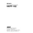
4) Focus Error Amplifier
The photo-detector outputs (A + C) and (B + D) are passed through a differential amplifier and an error amplifier, and then (A + C � B � D) is output from Pin 91 as the FE signal. The FE voltage low frequency component is : 16k (80k//300k) FE = (A + C � B � D) � � 10k 20k = (A + C � B � D) � 5 Using REFO as the reference, an S-curve of approximately 1.5 Vpp is obtained for the FE output. The final-stage amplifier cutoff frequency is 11.4 kHz.
90 D/A FE OFFSET CN101 A+C 10k 6 82 83 16k 48k 110k 80k R200 300k 91 FE
C210 220pF
20k
A/D TO DIG. EQ
84 13 B+D 85 10k 16k
48k 20k
Fig.4 : FOCUS ERROR AMPLIFIER
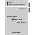
5) Tracking Error Amplifier
The photo-detector outputs E and F are passed through a differential amplifier and an error amplifier, and then (E � F) is output from Pin 93 as the TE signal. The TE voltage low frequency component is : TE = (E � F) � 224k (56k+27k) � 80k 38k
6) Tracking Zero Crossing Amplifier
TEC signal (the tracking zero crossing signal) is obtained by multiplying the TE signal four times. It is used for locating the zero crossing points of the tracking error. The zero cross point detection is done for the following two reasons : 1 To count tracks for carriage moves and track jumps. 2 To detect the direction in which the lens is moving when the tracking is closed (it is used on the tracking brake circuit to be described later). The TEC signal frequency range is 300 Hz to 20 kHz. TEC voltage = TE level � 4 Theoretical TEC level is 5.2V. The signal exceeds Drange of the operational amplifier and thus is clipped. It, however, can be ignored since this signal is used by the servo LSI only at the zero crossing point.
C211 100pF 92 D/A TE OFFSET 110k 80k 93 TE
= (E � F) � 5.7 (Effective LSI output is 5.0). Using REFO as the reference, the TE waveform of approximately 1.3 Vpp is obtained for the TE output. The final-stage amplifier cutoff frequency is 20 kHz.
CN101 F R215 F 9 86 27k 56k 224k 48k
38k
A/D TO DIG. EQ TE2 94 20k R210 0 C212
E R216 E 11 27k 87 56k 224k 48k 38k
60k
95 TEC 6800pF
4
Fig.5 TRACKING ERROR AMPLIFIER AND TRACKING ZERO CROSSING AMPLIFIER
|
|
|
> |
|