|
|
|
Who's Online
There currently are 5946 guests online. |
|
Categories
|
|
Information
|
|
Featured Product
|
|
|
 |
|
|
There are currently no product reviews.
 ;
some of the writing is a bit blur but the part in the schmatic was great and i have fixed the machine thanks
 ;
Well.. I'd searched for this manual and although I found many copies online I was pleased to find your website with a well balanced pricing system and easy to search and follow links. That together with the very quick response time was just what I was looking for.. being a very impatient tech.. ;-) I had the service manual in front of me within a short time.
Bookmarked.. and you can bet I will always come here first for my service & user manuals..
best regards
Ed(Tony) Foley
G7WHK
;
I will definitely be back for more information when I need it.
;
The service manual when downloaded and printed out was clear and easy to read. I would have liked to have been able to enlarge some details, but this was not possible as the file permissions did not allow this. The service was very good. The time taken from placing my order to downloading the document was only a few minutes.
;
The manual is useful for trouble shooting for an old instrument. It saved money,and let me enjoy DIY.
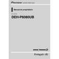
DEH-P840MP,P8400MP,P8450MP
- How to hold the Mechanical Unit
1. Hold the top and bottom frame. 2. Do not squeeze top frame's front portion too tight, because it is fragile.
Do not squeeze.
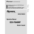
- How to remove the Top and Bottom Frame
1. When the disk is in "clamp" state, unlock Spring A (6 pieces) and Spring B (2 pieces), and unscrew screws (4 pieces). 2. Unlock each 1 of pawl at the both side of the frame, then remove the top frame. 3. Remove the Carriage Mechanical part in such way that; you remove the mechanical part from 3 pieces of Damper while slowly pulling up the part. 4. Now, the top frame has been removed, and under this state, fix the genuine Connector again, and eject the disk. (Caution) When you reassemble the Carriage Mechanical part, apply a bit of alcohol to Dampers. Top Frame
Carriage Mechanical Part
Bottom Frame
Damper
- How to remove the Guide Arm Assy
1. Unlock the spring (1 piece) at the right side of the assembly. 2. Unscrew screws (2 pieces), then remove the Screw Gear Bracket. 3. Shift the Guide Arm Assy to the left and slowly rotate it to the upper direction. 4. When the Guide Arm Assy rotates approximately 45 degree, shift the Assy to the right side direction and remove it.
Screw Gear Bracket Guide Arm Assy
Spring
70
|
|
|
> |
|