|
|
|
Who's Online
There currently are 5994 guests online. |
|
Categories
|
|
Information
|
|
Featured Product
|
|
|
 |
|
|
There are currently no product reviews.
 ;
Ottima qualità grafica e completo nelle notizie. Costo abbastanza contenuto.
;
Great and quick support. The maual was exactly what I was looking for and my problem
solved. Many thanks.
;
Very good service Within one day i received a pdf of the users manual and electric circuits so I was able to measure the different voltages in the printed circuit and find out the fault Payment was also reliable and easy.Without the manual i could not have repaired.So thanks to "Search for a manual"
 ;
you are doing great job guys.....my father ask me to find out the schematics of Sony KV25R1D to sort out the problem ..(he was electrical technician, and excperianced with TV and simillar stuff). finally he found the cause and change all necessary parts....now he has got working old dog..and is very happy!!... thank you all.. NB..he also saved the repair cost.
;
Perfect. Received my manual within 24 hours. Clear scan of the manual I needed. No problem.
1
2
3
4
1.1.3 Focus error amplifier
The photo-detector outputs (A + C) and (B + D) are passed through the differential amplifier and the error amplifier, and (A + C - B - D) is provided from the pin 135 as the FE signal. The low frequency component of the voltage FE is calculated as below. FE = (A + C - B - D) x 8.8k / 10k x 111k / 61k x 160k / 72k = (A + C - B - D) x 3.5 For the FE outputs, an S-shaped curve of 1.5 Vp-p is obtained with the REFO as the reference. The cutoff frequency for the subsequent stage amplifiers is 14.6 kHz.
A
1.1.4 RFOK circuit
This circuit generates the RFOK signal, which indicates the timing to close the focus loop and focus-close status during the play mode, from the pin 70. As for the signal, "H" is output in closing the focus loop and during the play mode.
B
Additionally, the RFOK becomes "H" even in a non-pit area, since the DC level of the RFO signal is peak-held in the subsequent digital block and compared at a certain threshold level to generate the RFOK signal. Therefore, the focus is closed even on a mirror-surface area of a disc. This signal is also supplied to the microcomputer via the low-pass filer as the FOK signal, which is used for protection and gain switching of the RF amplifier.
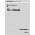
1.1.5 Tracking error amplifier
The photo-detector outputs E and F are passed through the differential amplifier and the error amplifier to obtain (E - F), and then provided from the pin 138 as the TE signal. The low frequency component of the voltage TE is calculated as below.
C
TEO = (E - F) x 63k / 112k x 160k / 160k x 181k / 45.4k x 160k / 80k = (E - F) x 4.48 For the TE output, TE waveform of about 1.3 Vp-p with the REFO as the reference. The cutoff frequency in the subsequent is 21.1 kHz.
CD CORE UNIT
PE5611B
TE A/D
+ -
Pickup Unit
D
P5 P10
+ -
TEOFF setup
+ 80k
138
TEO
47p
160k 137
TE-
E
11
11
E
132 112k 63k
45.36k
161k
VREF
+ 45.36k
+ -
139
TE2
2.7k
+
P1 P6
-
160k
160k 20k 60k 10000p 140
1000p
F
9
9
F
131 112k 63k
TEC
-
VREF
+
Inside TEC
E
Fig.1.1.3 TE
F
6
CX-3240
1 2 3 4
|
|
|
> |
|