|
There are currently no product reviews.
 ;
Just what I needed to repair my CT-F600, clear pdf, easy to tread and navigate
 ;
Yes, cost is low. And quality of some diagrams is low too.
;
Quick response.
Good quality.
Not large price of documents.
Thanks.
Dzięki.
;
All ok:
Good quality.
Quick response.
Not large price of documents.
Thanks
;
The manual was complete and extremely helpful in both diagnosing the problem I was having as well as fixing it. Excellent quality. I will getting additional manuals in the future.
1
2
3
4
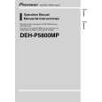
6.4 SYSTEM MICROCOMPUTER TEST PROGRAM
A
- PCL output
In the normal operation mode (with the detachable panel installed, the ACC switched ON, the standby mode cancelled), shift the TESTIN IC601 (Pin 86) terminal to H. The clock signal is output from the PCL terminal IC601 (Pin 37). The frequency of the clock signal is 468.75 kHz that is one 32th of the fundamental frequency. The clock signal should be 468.75 kHz ± 19 Hz. If the clock signal is out of the range, the X'tal (X601) should be replaced with new one.
B
6.5 OEL ADJUSTMENT
Adjustment point
KEYBOARD UNIT(SIDE B)
C
TP1 TP3 TP2
D
Digital Multi-Meter
<When the OEL Unit has been replaced> 1. Use VR1970 to adjust the resistance between TP1 and TP3 to 6.2 k�. 2. Use VR1971 to adjust the resistance between TP2 and TP3 to 6.2 k�.
E
F
52
DEH-P580MP/XN/UC
1 2 3 4
|