|
|
|
Who's Online
There currently are 5996 guests online. |
|
Categories
|
|
Information
|
|
Featured Product
|
|
|
 |
|
|
There are currently no product reviews.
 ;
Probably it never existed a 1081 official service manual from Commodore, it's look more like a NAPCEC service manual & diagrams compilation of the 1084 series and his variants, like the nap6523, 8cm505, 1084S, 1084P and obviously the 1081. It's more complete than other scans and the quality of the scans also are far superior. It has two circuit diagrams variants of the 1081, mono and stereo versions. It doesn't include a diagram for the Philips CM8500 or CM8501, they look like the 1081 but they are slightly different.
 ;
Rapid, clear well done as all the scheme I downloaded from this site. Great job very functional and very useful
;
Great copy of the manual, has all information required for servicing,
;
I work at an authorized service center and I can tell if a manual is as it should be. This one is. It may be a scan, but a very good one at that. The interesting part for me was the curcuit diagram which was scanned at high quality, making it as good as the original. I will definitely be back as a customer. I need not say this, but I will: the price was the best. Thank you owner-manuals.com .
;
really a very good manual even sometimes the quality is no so good as before still very readible and very very useful!
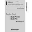
DEH-P410,P4100,P310
- Removing the Guide Arm Assy
1. Remove a connector, a spring A and B 2. Drive the Guide Arm Assy up aslant into rear side direction, then remove it from a Pin. Finally, drive the assembly approximately 45 degrees upward, then slide the assembly toward left side to remove it. Note : When assembling the guide arm assembly, route the cord inside the assembly. In this operation, care must be exercised so that cord may be caught by the gear.
Guide Arm Assy Section
A
B Pin
LO Arm Assy Section
- Removing the LO Arm Assy
1. Remove two Pins to dismount the LO Arm Assy.
- Removing the Control Unit and the Spindle Motor
1. Remove from the connector after mounting the short pin on the flexible PCB of the pickup unit. 2. Remove two Soldered joints, then remove two Screws A. 3. Remove two connectors and a Screw B. 4. Disengage the Control Unit from two Tabs, then dismount the unit by sliding it toward left. 5. Dismount the Spindle Motor.
Short Pin
Spindle Motor
B
Control Unit
A
A
68
|
|
|
> |
|