|
|
|
Who's Online
There currently are 5877 guests online. |
|
Categories
|
|
Information
|
|
Featured Product
|
|
|
 |
|
|
There are currently no product reviews.
 ;
I'm very satisfied with your manual service. Your website made it easy to locate the correct manual. Also the quality is great and I never had a problem reading the fine details.
Thanks again.
Jeff Miller
JM Electronics
 ;
Good quality service manual German user manual. German user manual This is a quality scan of a manual in excellent condition and is just as good as having the original manual in hand
;
The manual for Sony LBT-D505 component stereo system is was excellent , with schematics, parts layout and parts list as well as instructions for adjustments for each component. Print was clear even when enlarged.
;
It's exactly a complete and very useful manual with all details what I needed. Thank you!I will come back whenever I need your manuals or schematics.
;
I searched EVERYWHERE looking for the manual/s on this "extinct" amp. Owner-Manuals.com made it available and for nearly nothing. Thanx to them, I can decipher the unknown cables and sort them out. Thanx, Owner-Manuals.com!!
5
6
7
8
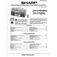
3. DISASSEMBLY
- How to hold the Mechanism Unit
1. Hold the top and bottom frame. 2. Do not squeeze top frame's front portion too tight, because it is fragile.
A
B
Do not squeeze.
- Removing the Upper and Lower Frames
1. With a disc clamped, remove the four springs (A), the two springs (B), the two springs (C), and the four screws. 2. To remove the upper frame, open it on the fulcrum A. 3. While lifting the carriage mechanism, remove the three dampers. 4. With the frames removed, insert the connectors coming from the main unit and eject the disc. Caution: Before installing the carriage mechanism in the frames, be sure to apply some alcohol to the dampers and set the mechanism to the clamp mode. Carriage Mechanism B Damper Lower Frame B Damper A Damper C
D
A C A
Upper Frame
A
C
A
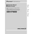
- Removing the Guide Arm Assy
1. Remove the upper and lower frames and set the mechanism to the clamp mode. 2. Remove the two springs. 3. Remove the two screws and bevel gear bracket. Note that the gears come off. 4. Slide the guide arm assy in the direction marked Spring with the arrow (1) and open it upwards. 5. At the angle of about 45 degrees, slide the guide arm assy in the direction marked with the arrow (3) to remove it.
E
F
Guide Arm Assy
Spring
CX-3110
21 7 8
5
6
|
|
|
> |
|