|
|
|
Who's Online
There currently are 5493 guests online. |
|
Categories
|
|
Information
|
|
Featured Product
|
|
|
 |
|
|
There are currently no product reviews.
 ;
I found the manual to be clear concise and complete. It was of immense assistance when removing the unit as the unit was over 22 years old and the wiring diagram was unobtainable from the manufacturer. The exploded drawings were clear as were the instructions and labels.
;
I will highly recommend this seller. They are honest, accurate, fast and responsible.
;
This manual was very good & was very helpful with repairs.
Always great & fast service from Owner's manual.
;
Very pleased with the quality of the scan. No complaints whatsoever.
 ;
I liked the product. I would use their sevices again.
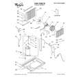
DEH-3400R,2460R,2430R
- How to hold the Mechanical Unit
1. Hold the top and bottom frame. 2. Do not squeeze top frame's front portion too tight, because it is fragile.
Do not squeeze.
- How to remove the Top and Bottom Frame
1. When the disk is in "clamp" state, unlock Spring A (6 pieces) and Spring B (2 pieces), and unscrew screws (4 pieces). 2. Unlock each 1 of pawl at the both side of the frame, then remove the top frame. 3. Remove the Carriage Mechanical part in such way Carriage Mechanical that; you remove the mechanical part from 3 pieces Part of Damper while slowly pulling up the part. 4. Now, the top frame has been removed, and under this state, fix the genuine Connector again, and eject the disk. (Caution) When you reassemble the Carriage Mechanical part, Bottom Frame apply a bit of alcohol to Dampers. Damper Top Frame
- How to remove the Guide Arm Assy
1. Unlock the spring (1 piece) at the right side of the assembly. 2. Unscrew screws (2 pieces), then remove the Screw Gear Bracket. 3. Shift the Guide Arm Assy to the left and slowly rotate it to the upper direction. 4. When the Guide Arm Assy rotates approximately 45 degree, shift the Assy to the right side direction and remove it.
Screw Gear Bracket Guide Arm Assy
Spring
53
|
|
|
> |
|