A great copy of the manual, and the only one I could find anywhere on the net! The circuit diagrams are easily readable, all component values marked and easy to see. A highly appreciated download!
The TEAC A-1500's Service Manual was instrumental in reviving this classic reel-to-reel. Not only does it have the schematics, exploded parts diagram and parts list, it also provided mechanical adjustment information that approximate factory default settings.
Text excerpt from page 44 (click to view)
1
2
3
4
7. GENERAL INFORMATION
7.1 DIAGNOSIS
A
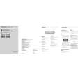
7.1.1 DISASSEMBLY
- Removing the Case (not shown) 1. Remove the Case.
- Removing the CD Mechanism Module (Fig.1)
CD Mechanism Module
1
B
Remove the four screws.
Disconnect the connector and then remove the CD Mechanism Module.
1 1
- Removing the Grille Assy (Fig.1)
2
Release the two latchs and then remove the Grille Assy.
1
C
2
1
2
Grille Assy
- Removing the Tuner Amp Unit (Fig.2)
Fig.1
1
D
Remove the screw.
2 2 2
2 3 4
Remove the three screws.
Straighten the tabs at three locations indicated. Remove the screw and then remove the Tuner Amp Unit.